Contents
Introduction
In the previous post the main characteristics of the EMS (Energy Management System) Bus from Buderus were exposed. In this post, the hardware and software used to connect and exchange information with the boiler through the EMS Bus, named Calduino, will be presented. In the next post you will see how to import in weeWX the information gathered and how to control from an HTTP web page the boiler configurations.
Hardware
To reproduce this tutorial you will need three hardware components:
- An EMS Bus – UART interface circuit that will convert the EMS Bus signals to TTL levels.
- An RN 171 XV WiFly Module from Microchip (formerly Rovin Networks) connected to the domestic LAN.
- An Arduino Mega 2560 Rev3 that will act as a bridge between sent and received commands over WiFly’s TCP/IP socket and the EMS Bus.
EMS Bus – UART Interface Circuit
The EMS Bus cannot be connected directly to the Arduino Serial Ports (UARTs). First of all the bus signals have to be TTL-converted. To do so you should build a small circuit. If it it is your first experience with electronics, don’t worry about this step. I am basicly a software guy, have almost forgotten all my electrical engineering lessons and soldering has always been a big drama for me. Nevertheless, I was able to build the circuit and integrate it successfully with the rest of components.
The schema of the circuit is depicted in the following diagram: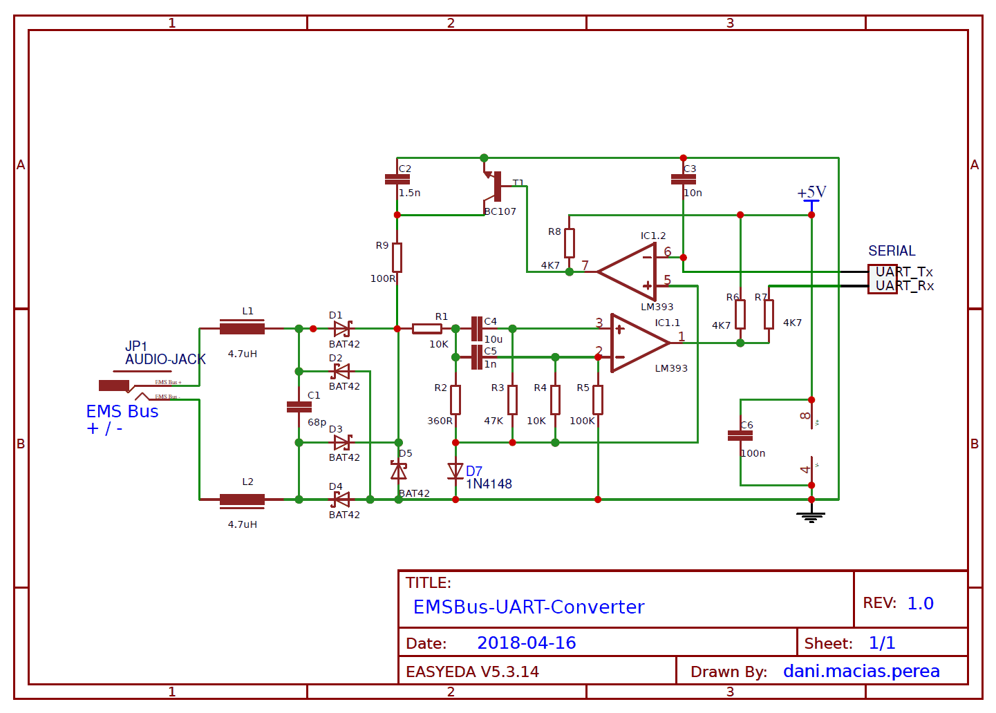
You can download a PDF file of the schema under this link or access the online version in easyeda.com. The schematic is an adaptation from this NetIO-EMS-Converter and bbqkees circuit, which is based in a reverse engineered schematic of a Buderus Service key. The TTL-converted signals (UART_Rx and UART_Tx) can be directly connected to one of the the Arduino Serial Ports. It does not matter which EMS bus pin is connected to each pin. The bridge rectifier (4 BAT42 diodes) will make both orientations work.
Make sure to power the LM393 Dual Comparator with the 5 V and ground lines. Although not noted in the diagram, the power rating of resistor R9 should be of 1 W. You can use this shopping cart list in reichelt.com to acquire easily the needed components.
RN 171 XV WiFly Module
Due to the physical situation of my boiler, a simple connection between the Raspberry/domestic router and this circuit using a RJ45 arduino shield was not an option. That should not be a big problem seeing that nowadays there are plenty of inexpensive ESP 8266 WiFi modules. However I decided to use a more robust alternative taking advantage of the fact that I already had the WiFly module unused at home.
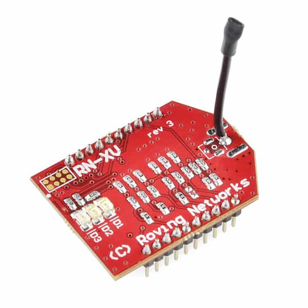
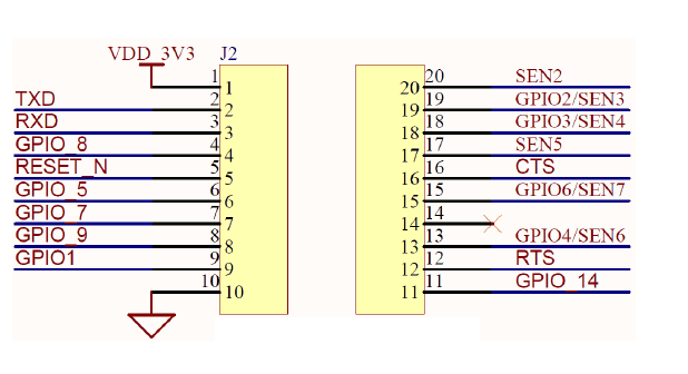
The formerly Rovin Networks 171 XV module (nowadays Microchip) incorporates 802.11 b/g radio, 32 bit processor, TCP/IP stack, real-time clock (updated via NTP), crypto accelerator (WEP, WPA-TKIP, WPA2-AES compatible), power management unit and analog sensor interface. It has a relative low power consumption with 4 µA in sleep mode, 15 mA in standby, 35 mA in reception and 185 mA in transmission at the maximal power of 12 dBm (the transmission power is configurable from 0dBm to 12dBm), being its operating voltage 3,3 V. The module has 8 general purpose digital I/O, 3 analog sensor inputs and a TTL UART interface that can reach up to 464 Kbps. It is mounted in on a XBEE compatible connector as shown in the next image:
The RN-XV module is pre-loaded with Roving firmware to simplify integration and minimize development time. It can be easily configured and managed over the UART or wireless interface (via Telnet) using simple ASCII commands. The module has two modes of operation: Data mode and Command mode. In Data mode, the module can accept incoming connections or initiate outgoing connections. To configure parameters and/or view the current configuration, the module must be placed into Command mode.
The first time you power up the module, an initial configuration should be performed to save your domestic network information.
Entering WiFly Command Mode
By default, the module is in Data mode after power-up. Commands must be sent to the module through the UART or remotely via Telnet:
- To access the UART interface you should use an USB to TTL converter. If you don’t have one (it costs less than 10 €), you can use your Arduino board. There are several ways to use an Arduino as USB to TTL Converter, the easiest one is to connect the Reset and Ground Pin of the board with the help of a jumper wire. Now you can use the Arduino’s RX and TX pins for communication with the RN-XV. The serial communications settings should match the RN module’s stored settings (default are 9.600 bauds, 8 bits, No parity, 1 Stop bit, Hardware Flow Control disabled). Rovin Networks recommends to use Tera Term, however I have also used PuTTY successfully.

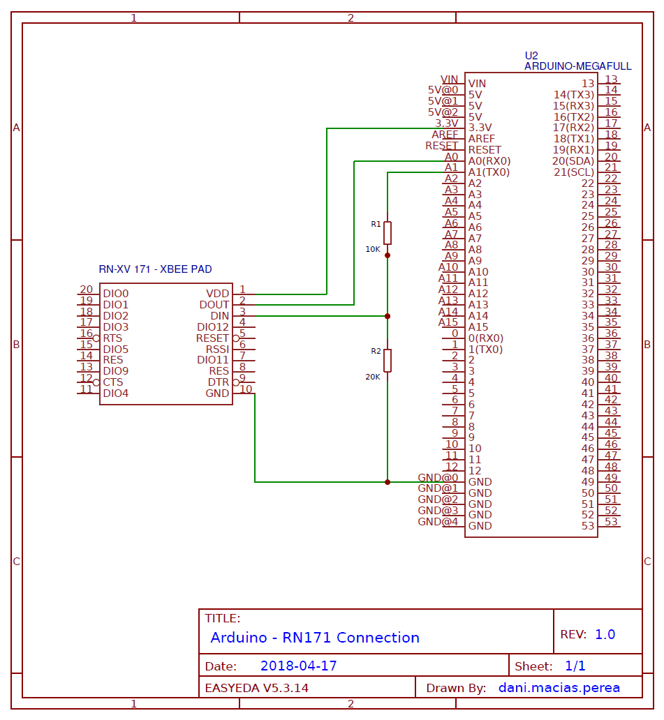
Warning: the RN-XV TX and RX Pins are 3,3 V tolerant. If you use an Arduino whose operating voltage is 5 V, you may use a level shifter in the TX Pin (RN-XV RX Pin). Otherwise you risk to damage your RN-XV module. On the other hand, the RN-XV Transmissions (TX) at 3,3 V signals will be considered logical ones in the 5 V Rx Arduino. Follow this schema to connect your RN-XV module though UART.
- To connect via Telnet, you should first boot the RN-XV in ad-hoc mode by pulling up PIN 8 – GPIO 09 (connecting it to 3,3 V line). Upon power up with GPI O9 high, the WiFly module creates an ad hoc network with default settings (these settings override any saved configuration). From your computer, connect to the WiFly-GSX-XX network and wait until an IP in the subnet 169.154.X. X is assigned (it may take a while). This open network does not require a pass phrase or pass key. Once connected, do telnet into the WiFly module on port 2000 using the following command:
telnet 169.254.1.1 2000. If everything is working fine, the module issues the response *HELLO*.
In both ways, sending the escape sequence of three dollar signs, $$$, causes the RN module to enter Command mode. The three dollar sign ($) characters must be sent in succession with no additional characters before or after. A carriage return or line feed must not be sent after entering $$$ to enter Command mode. After entering the sequence, the RN module replies with CMD to indicate it is in Command mode.
Once in Command mode, the RN module can be configured using simple ASCII commands, with each command ending with a carriage return. Most valid commands return AOK; invalid commands return a ERR description. To exit Command mode, send an exit command by typing exit following by a carriage return. The RN module responds with EXIT, indicating that it has exited Command mode and has entered Data mode.
Wifly Commands
Once in the command mode, you should perform an initial configuration to connect the device with your domestic network.
To do so type the following commands:
set wlan ssid *your SSID*
set wlan passphrase *your WiFi password*
Note: Avoid using non alphanumeric characters in the SSID or passphrase. I have assumed that your domestic network will use WPA or WPA2. In the improbable case that you still use WEP, use set wlan key *10/26 key characters*.
set wlan join 1
It sets the policy for automatically associating with network access points (0 – Manual, 1 – Automatic, 7 – Create Access Point).
set ip dhcp 1
To solve the IP address and gateway with DHCP protocol.
save
This command saves the settings in a configuration file. Any changes made must be saved using the save command or the RN module will load the previous settings upon reboot or power-up. When the system boots, all configuration data is loaded into RAM variables from the configuration file.
The Set commands only modify the RAM copy of the system variables. Some commands. such as setting the SSID, require a save and reboot before taking effect because they operate only upon power-up. Other commands can be changed on-the-fly. So to apply the configuration (and close the connection) run:
reboot
After a few seconds your device should be connected to your domestic WLAN. If you were forcing ad-hoc mode stop pulling up PIN 8 before restarting. To reconnect via telnet you should find out which address has been assigned to the device.
The RN module is really powerful. In theory, with its built-in TCP/IP stack and GPIO access, it can act as an standalone device. It should be even possible, in theory, to create a serial port using its UART or two GPIOs (software serial) to talk directly with the EMS Bus. However, I have decided to use the module though the Arduino Mega. By doing so, I think I have acquired more flexibility and reliability in the project.
You can access the full commands specification of the RN-XV module in this document.
Updating Wifly Firmware
There are several versions of the firmware, being the oldest ones somehow buggy. Before starting a project like this, it is a good idea to update it. The device should be able to perform an on the fly update. However, Microchip acquired Roving Networks and the default FTP server used by the module no longer exists. To solve this issue, before updating, you should change the FTP address used. To do so, once the device is connected to your domestic LAN and has internet, access the command mode and do:
set ftp address 0
It will just delete the IP address of the FTP server.
set dns backup rn.microchip.com
The FTP client uses the backup string to download the firmware via the ftp update command.
save ftp

update
It will save the parameters in a configuration file named ftp and will try to perform the module update. After a few seconds you should be seeing something like this:
<2.31> ftp update
<2.31> FTP connecting to 198.175.253.161 FTP file=34 …………………………………………………………..
FTP OK.
UPDATE OK
REBOOT
Then your device should be connected again and updated to last version 4.83 (april 2018).
Wifly LED Status
In the following table the meaning of the module LEDs is described.
| Condition | Red LED – D1 | Yellow LED – D2 | Green LED – D3 |
| On solid | – | – | Connected over TCP |
| Fast blink | Not associated | Rx/Tx data transfer | No IP address |
| Slow blink | Associated, no Internet | – | IP address OK |
| Off | Associated, Internet OK | – | – |
Arduino Mega
Theoretically, to build this project, an Arduino board with only one serial port is needed. This port should be connected to the EMS Bus – UART interface. The WiFly module is known to work correctly from software serial ports. However, developing Arduino code in a hardware with only one serial port would have been harder, making it unable to debug/monitor the code and forcing to disconnect everything every time you want to upload new software versions.
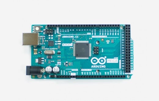
For this reason I decided to use an Arduino Mega 2560 V3, which has 4 times mores SRAM and UARTs than Arduino One (8 KBytes – 4 UART ports).
Calduino: Puting it al together
The figure below shows the full schema of the project, putting all the components together. You can download a PDF file of the schema under this link or access the online version in easyeda.com. Its name, Calduino, comes from latin word calor (heat) and arduino.![]()
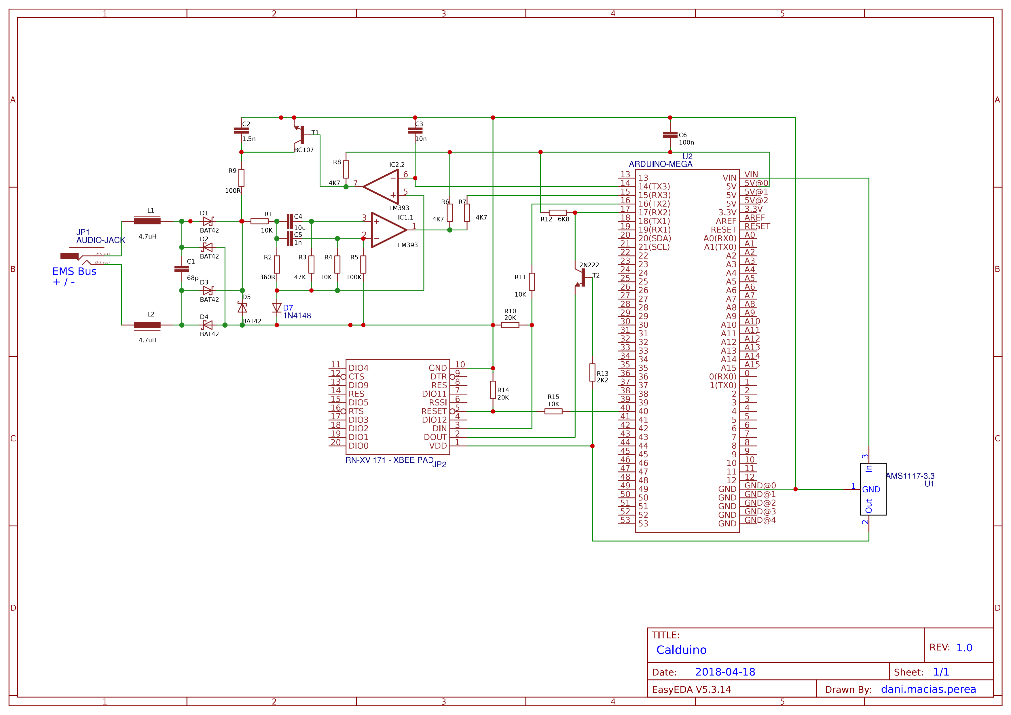
- Calduino is powered using a 12 V / 1000 mA power supply unit connected to the power jack of the Arduino Mega. It should be possible to power the whole circuit using the 12 V available in the EMS Bus. Read bbqkees Github to know more about this issue.
- The EMS Bus – UART interface circuit is powered by the Arduino Mega 5V pin. This pin outputs a regulated 5V from the AMS1117 on the board, which has a maximum output current rating of 1A. This voltage is split up within the board for other components and some energy is lost as heat. So, if nothing else is connected, from the 5V pin a current up to 700 mA can be obtained, more than enough to power the interface circuit. Maximal power consumption in the circuit should happen when writing in the EMS Bus. The 100 Ohms / 1 Watt resistor pulls the line down consuming nearly 80 mA.
- As can be seen in the schema, the RN-XV 171 module is powered by an AMS1117-3.3 module with 3,3 V. This regulator is connected to the Arduino Mega Vin pin, which contains the input voltage of the board. The 3.3V pin in the Arduino Mega cannot be used to supply energy to the WiFly module directly. It has a maximum current draw of 50 mA, in any case insufficient for this purpose, requiring up to 185 mA when transmitting at maximum power.
- As previously commented, the RN-XV TX and RX Pins are 3,3 V tolerant. I have used a level shifter for both pins, despite being only necessary for the RN-VX RX Pin. In the RN-VX TX Pin I have used an NPN transistor 2N2222 with two resistors.
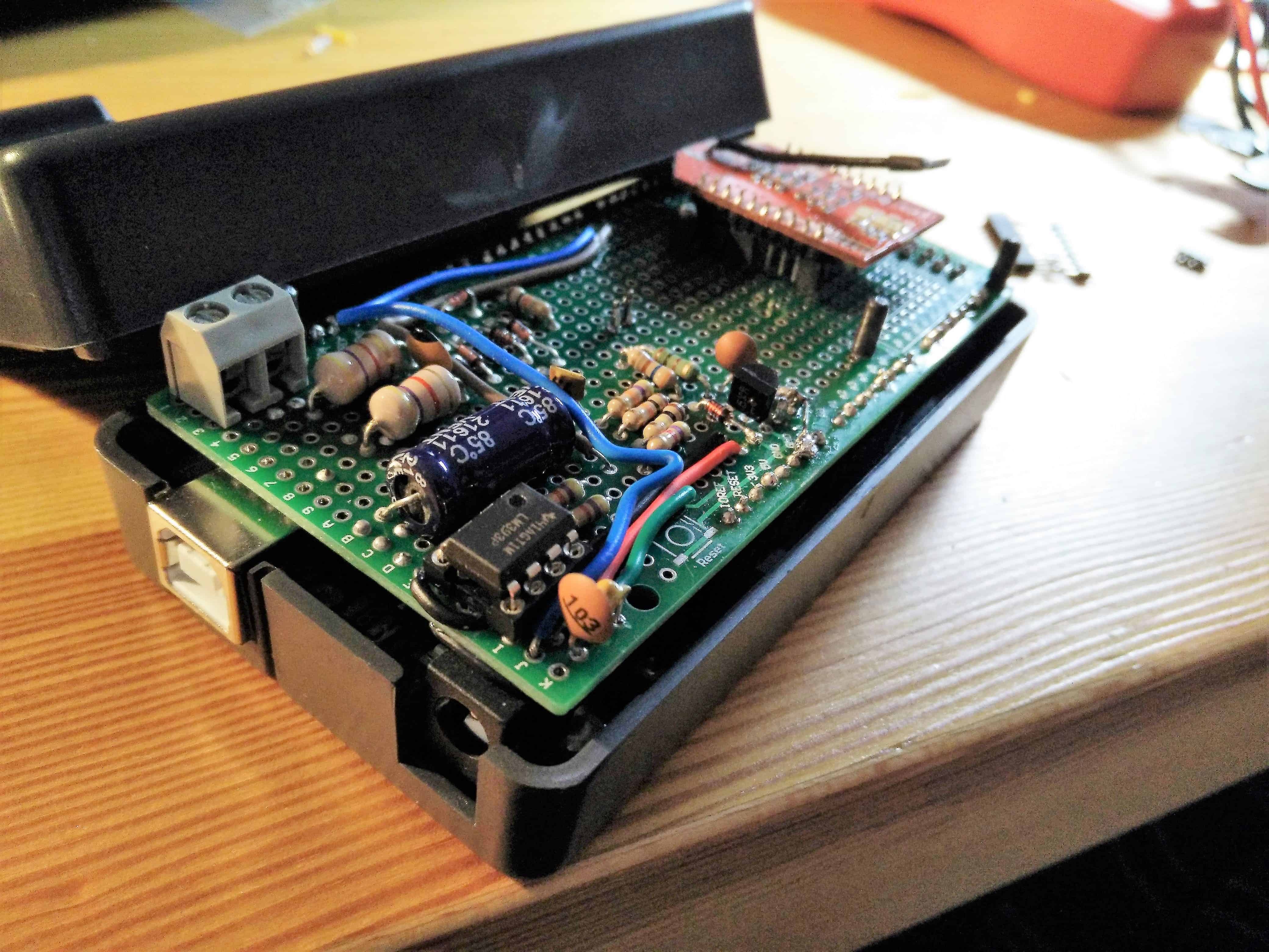
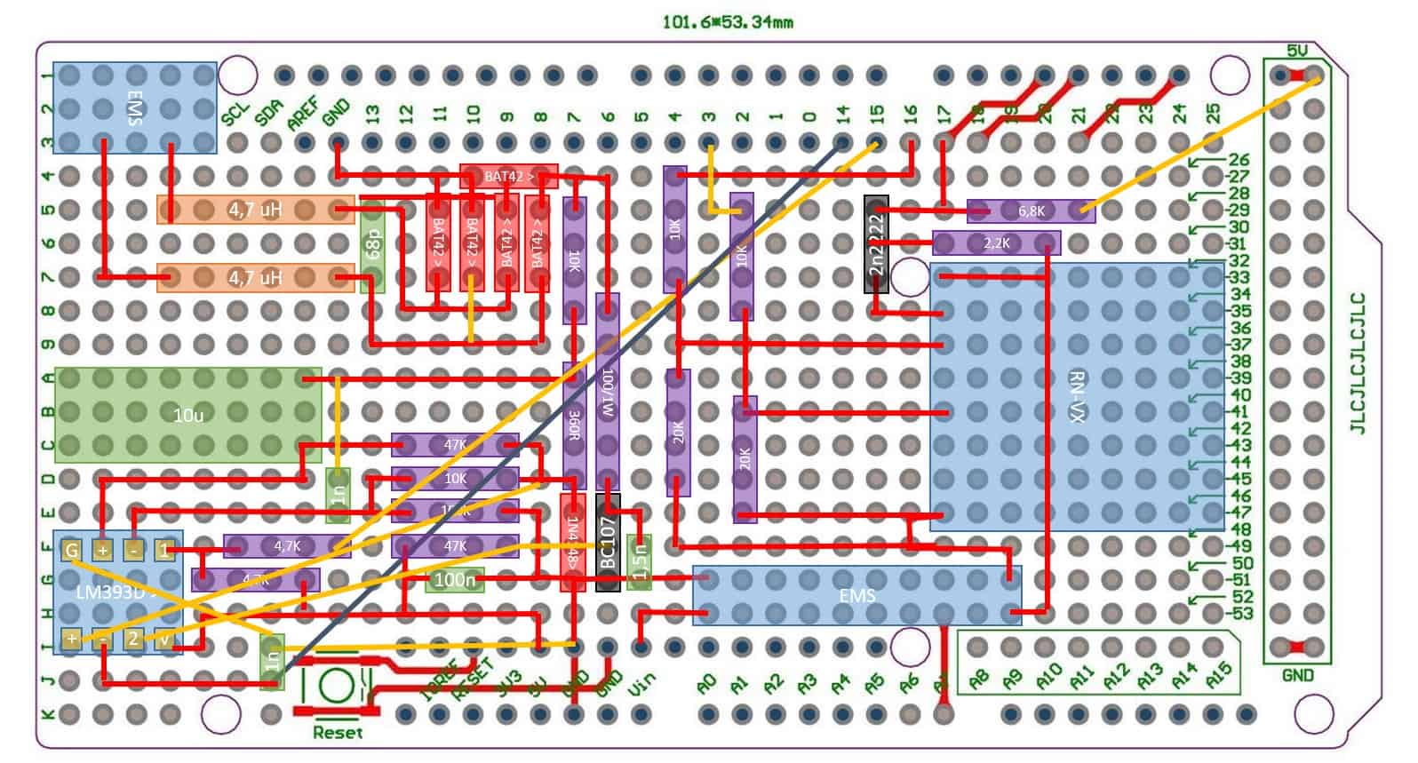
- The circuit has been built in a prototype PCB for Arduino Mega Shield Board available here. The board is well built with full pipes and printing for all I/O pins.
- To encapsulate the circuit and its components I have used the following case, available in Amazon. It is high enough to fit an Arduino Mega with upper shield. Moreover, it has an specific slot for an ethernet socket that can be used to connect the EMS-Bus wires.
- The RN-XV 171 reset pin is connected, though a level shifter, to Arduino Mega Pin 40. A low pulse of at least 160 μs should be applied to perform the module reset.
- In the circuit is drawed a bipolar NPN transistor BC 107A. If you can’t find it in your local distributor, it can be replaced by the more modern and common BC 547.
Software
To make this project easily portable I have developed a C++ library with the most common functions offered by the EMS Bus. The last version of Calduino library is available in my Github page. This library, as well as WiFlyHQ library are used by the sketch CalduinoWiFly.ino to connect wirelessly with the EMS Bus.
Calduino Library
Its documentation can be found in this link. Some design notes:
- Calduino class has two references to serial ports: Calduino Serial is used to communicate with the EMS Bus. Debug Serial, when debug is activated, is used to show the output of the operations performed. If referenced with the serial port used by WiFly, output will be redirected to WiFly and sent over the opened TCP/IP connection. If referenced with an standard serial port, the output will be seen in the serial monitor.
- In order to communicate with the EMS Bus through the UART ports some slight changes should be made in the Hardware Serial Library. As explained here, the EMS Bus ends each data package with a break, an 11-bit long “zero” written in the bus. Although the Arduino microcontroller is able to detect break conditions, there is no function in the Serial Library to manage them. On the other hand, there is also no way to send a break whenever we want to write something in the EMS Bus. To accomplish that, new functions/adaptations have been performed in class Calduino Serial. It is only compatible with Atmel ATmega microcontrollers and is based in 2012 Serial Library version. Thanks to bbqkees for providing this. I have done some work porting this functions to the most recent serial library, I hope to update it in the near future.
- The serial buffer size is defined in Calduino.h file. Watch out with this value, each serial port consumes this quantity of bytes in memory! I have not been able to read more than 32 bytes in a data frame, so if you are not using WiFly maybe this is a suitable value for you. However, some WiFly HTTP requests need up to 48 bytes. Consider this when setting this value. Due to this read limit, the function getEMSCommand splits commands in a maximum of 32 bytes.
- All the EMS Bus related operations have a timeout to avoid hanging the sketch.
- The library has been relatively optimised to reduce the quantity of memory consumed. All the data structures, as well as the strings exchanged in the XML messages are stored in program memory. Of course there is still some room for improvement. For instance, replacing the enumeration data types by defines will save nearly 100 bytes, making the code harder to read at the same time.
CalduinoWiFly sketch
As previously commented, the sketch developed (CalduinoWiFly.ino) will have a passive role and will not start any operation by itself. It will be used as a bridge between the web server (running on Raspberry Pi) and the EMS Bus. This way, if a user sets the thermostat temperature to 20℃ in the web page formular, the server will send a set command to Calduino and will wait until it is performed.
Calduino commands are sent in HTTP GET requests. The parameters needed by the command, such as the type of operation or the temperature requested, are coded in the query string. There are three types of Calduino commands:
- Get commands (operation code from 00 to 29) will send information in XML format regarding EMS devices such as UBA boiler, heat circuits, mixer, etc.
- Set commands (operation code from 30 to 50) performs a change of an specific configuration in an EMS device. The operation results will also be sent in XML format.
- Calduino commands (operation code 60 or higher) will request information and manipulate the Arduino Circuit (restart WiFly, get statistics, etc.).
Command List
The following table summarises the commands supported by Calduino. For more detail in the parameters used, have a look at the comments in the code or see the corresponding section in this entry:
| Id | Command Name | Example | Description |
|---|---|---|---|
| 00 | Get RC Datetime | calduino/?op=00 | Get RC Datetime Datagram |
| 01 | Get UBA Working Time | calduino/?op=01 | Get UBA Working Time Datagram |
| 02 | Get UBA Monitor Fast | calduino/?op=02 | Get UBA Monitor Fast Datagram |
| 03 | Get UBA Monitor Slow | calduino/?op=03 | Get UBA Monitor Slow Datagram |
| 04 | Get UBA Parameter DHW | calduino/?op=04 | Get UBA Parameter DHW Datagram |
| 05 | Get UBA Monitor DHW | calduino/?op=05 | Get UBA Monitor DHW Datagram |
| 06 | Get Flags DHW | calduino/?op=06 | Get Flags DHW Datagram |
| 07 | Get Working Mode DHW | calduino/?op=07 | Get Working Mode DHW Datagram |
| 08 | Get Program DHW | calduino/?op=08 | Get Program DHW Datagram |
| 09 | Get Program Pump DHW | calduino/?op=09 | Get Program Pump DHW Datagram |
| 10 | Get Working Mode HC 1 | calduino/?op=10 | Get Working Mode HC 1 Datagram |
| 11 | Get Monitor HC 1 | calduino/?op=11 | Get Monitor HC 1 Datagram |
| 12 | Get Program User 1 HC 1 | calduino/?op=12 | Get Program User 1 HC 1 Datagram |
| 13 | Get Program User 2 HC 1 | calduino/?op=13 | Get Program User 2 HC 1 Datagram |
| 14 | Get Working Mode HC 2 | calduino/?op=14 | Get Working Mode HC 2 Datagram |
| 15 | Get Monitor HC 2 | calduino/?op=15 | Get Monitor HC 2 Datagram |
| 16 | Get Program User 1 HC 2 | calduino/?op=16 | Get Program User 1 HC 2 Datagram |
| 17 | Get Program User 2 HC 2 | calduino/?op=17 | Get Program User 2 HC 2 Datagram |
| 18 | Get Working Mode HC 3 | calduino/?op=18 | Get Working Mode HC 3 Datagram |
| 19 | Get Monitor HC 3 | calduino/?op=19 | Get Monitor HC 3 Datagram |
| 20 | Get Program User 1 HC 3 | calduino/?op=20 | Get Program User 1 HC 3 Datagram |
| 21 | Get Program User 2 HC 3 | calduino/?op=21 | Get Program User 2 HC 3 Datagram |
| 22 | Get Working Mode HC 4 | calduino/?op=22 | Get Working Mode HC 4 Datagram |
| 23 | Get Monitor HC 4 | calduino/?op=23 | Get Monitor HC 4 Datagram |
| 24 | Get Program User 1 HC 4 | calduino/?op=24 | Get Program User 1 HC 4 Datagram |
| 25 | Get Program User 2 HC 4 | calduino/?op=25 | Get Program User 2 HC 4 Datagram |
| 26 | Get MM10 Monitor | calduino/?op=26 | Get MM10 Monitor Datagram |
| 29 | Get All Monitors | calduino/?op=29 | Get UBA Monitor Fast, Slow and Working Time. DHW, HC1, HC2 and MM10 Monitor and DHW, HC1, HC2 Working Mode and Program 1 Datagrams |
| 30 | Set Working Mode HC | calduino/?op=30 &hc=X&wm=Y |
Set the working mode Y in the heating circuit X:
|
| 31 | Set Temperature HC | calduino/?op=31 &hc=X&wm=Y&tp=ZZ |
Set temperature ZZ for working mode Y in the heating circuit X:
|
| 32 | Set Program HC | calduino/?op=15 &hc=X&pr=YY |
Set in heating circuit X program YY:
|
| 33 | Set S/W Threshold HC | calduino/?op=33 &hc=X&tp=ZZ |
Set in heating circuit X summer/winter threshold in ZZºC:
|
| 34 | Set RC35 Night Setback | calduino/?op=34 &hc=X&wm=Y |
Set in heating circuit X setback mode Y:
|
| 35 | Set Out Night Temperature Threshold HC | calduino/?op=35 &hc=X&tp=(Z)ZZ |
Set in heating circuit X outdoor temperature threshold to switch between shutdown and reduced operation mode to (Z)ZZ℃:
|
| 36 | Set Room Temperature Offset HC | calduino/?op=36 &hc=X&tp=(Z)ZZ |
Set in heating circuit X temperature offset (Z)ZZ℃:
|
| 37 | Set Pause Mode HC | calduino/?op=37 &hc=X&h=ZZ |
Set in heating circuit X pause mode for ZZ hours:
|
| 38 | Set Pause Mode HC | calduino/?op=38 &hc=X&h=ZZ |
Set in heating circuit X party mode for ZZ hours:
|
| 39 | Set Holiday Mode HC | calduino/?op=39 &sd=DD&ed=DD &sm=MM&em=MM &sy=YY&ey=YY |
Program in heating circuit X holiday mode between the starting and ending dates:
|
| 40 | Set Home Holiday Mode HC | calduino/?op=40 &sd=DD&ed=DD &sm=MM&em=MM &sy=YY&ey=YY |
Program in heating circuit X home holiday mode between the starting and ending dates:
|
| 41 | Set Working Mode DHW | calduino/?op=41 &wm=Y |
Set Domestic Hot Water working mode to Y:
|
| 42 | Set Working Mode Pump DHW | calduino/?op=42 &wm=Y |
Set Domestic Hot Water Pump working mode to Y:
|
| 43 | Set DHW Temperature | calduino/?op=43 &tp=ZZ |
Set Domestic Hot Water temperature to ZZ:
|
| 44 | Set TD DHW Temperature | calduino/?op=44 &tp=ZZ |
Set Domestic Hot Water thermal disinfection temperature to ZZ:
|
| 45 | Set Program DHW | calduino/?op=45 &pr=YYY |
Set in DHW program YYY:
|
| 46 | Set Program Pump DHW | calduino/?op=46 &pr=YYY |
Set in DHW Pump program YYY:
|
| 47 | Set WW One Time | calduino/?op=47 &wm=Y |
Set Domestic Hot Water one time function to Y:
|
| 48 | Set Working Mode TD DHW | calduino/?op=48 &wm=Y |
Set thermal disinfection Domestic Hot Water working mode to Y:
|
| 49 | Set Day TD DHW | calduino/?op=49 &d=D |
Set thermal disinfection Domestic Hot Water program on days D:
|
| 50 | Set Hour TD DHW | calduino/?op=50 &h=HH |
Set thermal disinfection Domestic Hot Water program at hour HH:
|
| 51 | Set RC35 Switch Point | calduino/?op=51 &pr=Y&sp=XX&on=Z &d=D&h=HH&m=MM |
Set switch point XX in program Y to Z status the day D at time HH:MM:
|
| 60 | Get Calduino basic statistics | calduino/?op=60 | Basic Calduino status |
| 61 | Get Calduino advanced statistics | calduino/?op=61 | Full Calduino status |
| 70 | Restart WiFly module | calduino/?op=70 | Restart the RN-XV WiFly module |
Note: calduino is assumed as the host name of the device where Arduino is running. I recommend to configure your DHCP server to assign a static IP to calduino linked to its MAC address as explained here.
Using Calduino
Get commands are very easy to use. Just send the request and, after a few seconds, you will receive an XML with the information asked. For instance:
curl calduino/?op=0230.7 0 0 0 0 0 0 0 0 30.6 0.0 1.2 48 72 203.0
In the first versions of the library I used to include a return tag to include current timestamp in Unix Epoch Time using the RN-XV module Real Time Clock (RTC). However, since the synchronisation with SNTP (Simple Network Time Protocol) servers is not stable and the internal RTC has a very big deviation, I decided to remove this functionality. Only in case there is an error with the EMS command, the message will include a return tag with 0 value.
Set commands are specific for each operation. Have a look at Command List Table to see which parameters are needed for each operation. For instance, in order to set the DHW (Domestic Hot Water) to 50℃ send the following request :
curl calduino/?op=43&tp=5050
Where:
- op: is the operation code and identifies the command. It always has two numeric characters.
- tp: is the requested temperature in Celsius.
Calduino will then perform the set operation and check if the value has been correctly updated. If the test is positive it will return the updated value. Otherwise the answered XML will only contain a return tag with 0 as value.
You can try this behaviour by setting the DHW temperature outside its limits:
curl calduino/?op=43&tp=990
Some comments regarding the code
- Wifly whatchdog: due to some connectivity problems at the beginning of the project, a watchdog was implemented to check every 5 minutes if WiFly was still associated with the local network (WLAN). In case it was not, it reconfigured the RN-XV module (even restarting it) to ensure that the connection was correctly retaken. Later on I decided to remove this functionality and to connect the power supply to a Radio Frequency controlled socket (433 Mhz). By doing so, when something is not working properly, the whole circuit can be restarted.
- Main Loop: as you can see, the main loop does nothing but waiting for a connection. Calduino will not initiate any connection by itself. When there is new data to be read, Calduino will search if the query string received matches any of the supported commands. In this case, it will execute the requested command. Otherwise it forces the closing of the connection and waits one second to restart the loop.
- RN-XV RTC Problems: The RN-XV module incorporates an internal clock (Real Time Clock) and functions to syncronize with SNTP servers. As previously commented, I started using the RTC to timestamp the XML files sent as answers in every command. This way, when importing the boiler information in weeWX, the old or already imported data could be discarded. I have been using WiFly NTP functions for a year and found two issues:
- First of all, it is only compatible with SNTP servers. And I am not really sure why, but it does not work with all SNTP servers available in pools. Some may work, some other may not. Moreover, the server is identified by his IP so there can exist down times where your unit cannot get synchronised. A local server could be a solution, but again, I did not get to synchronise the module time with a local NTP server installed in a Raspberry Pi.
- Secondly and more importantly, the internal clock of my RN-XV module drifts quite a lot. I don’t know if it is related to the power source used, but it gradually desynchronizes at a rate of nearly 0,5 minutes per hour.
Due to this two problems, I have finally decided not to rely on the time provided by the module. The version available in Githut does not configure the NTP Server and does not synchronise its internal clock. Instead of that, the getCalduinoStats operation will include, in the RTC tag, the seconds running using millis() function. The service that requests and imports the XML files will be in charge of updating the Return tag and replacing this uptime by the real epoch time.
dear Dani,
thanks for helping me out a little bit more to understand the EMS bus. Already have a bbqkees interface and i am working to put the bbqkees EMSbusExample1 together with a modbusIP with WZ5100 shield. It would be nice to do it with your CalduinoExample too. Don’t know if it is working on a Nefit enviline 9 heat pump, it has the EMS bus and thermostat moduline 1010.
have to find out this summer.
Hello Gertjan,
I am glad you found this post useful. I have searched some information about your moduline 1010, although being everything in dutch I think it has both EMS and Open therm Bus so very probably you will be able to connect with your boiler. In the instructions it talks about EMS 2.0, which I don’t know if corresponds with EMS Plus or is something else…
Anyway, have fun with the project!
Dani
Hello Dani,
thanks for your great work! Currently I build the EMS-Bus-UART-Converter according to your scheme. In your shopping list is the transistor 2N 3906, which is a PNP type. Is that correct, because in the schema is a BC107 marked and that is an NPN type?
Greetings from Austria
Friedl
Hello Friedl,
Sorry, it is a mistake! I bought the 2N 3906 transitor for another project and forgot to remove it from the list.
Regarding the BC 107 transistor, I copied the reference from emswiki design. However, I have remembered that in my circuit I finally replaced it by a BC 547B (new version with the same chip but in a modern epoxy case and with a doubled allowed thermal power).
I have updated the list with this item and will try to change the references to the new transistor.
Thanks for pointing it out und viel Erfolg!
Dani
Hola Dani,
Ante todo, agradecerte que compartas tus conocimientos y el trabajo que has realizado, que veo que ha sido mucho.
Solo comentarte una duda que tengo, necesito comunicarme con una caldera Junkers, que acepta el protocolo EMS. Pero me gustaría que fuese con un arduino (Arduino ethernet) con ethernet (Siendo arduino el servidor) y no con Wifly, ya que me gustaría que otro dispositivo solo funcionase como cliente.
¿Podrias ayudarme?
Mil gracias.
Un saludo.
Hola Sebastián,
Creo que la adaptación es relativamente sencilla. La librería Calduino que puedes encontrar en Github usa dos puertos series. El primero, Calduino Serial, es usado para comunicarse con el EMS Bus. El segundo, Debug Serial, puede ser usado para debugar y ver la salida de las operaciones realizadas por el monitor del puerto serie si el modo debug está activado. Si no está activado el flag debug, reenvía la salida de las operaciones por ese puerto. En mi caso WiFly usa un puerto serie para comunicarse con arduino, por lo que al referenciarlo a Calduino Serial, la salida de las operaciones se envía directamente a través de la conexión TCP/IP abierta. En tu caso entiendo que tu módulo de Ethernet está conectado a arduino a través de SPI. Creo que tendrás que usar algún tipo de código que reenvíe el contenido del puerto serie al cliente de Ethernet conectado en cada momento. Parece que esta librería hace algo similar a lo que necesitas.
En el sketch que uso arduino actua también como servidor, aceptando operaciones y enviando posteriormente la respuesta. Échale un vistazo aquí.
Por otro lado, Bbkques tiene un proyecto similar usando directamente un shield Ethernet que seguro que te puede servir de inspiración. Incluso si tu idea es hacer pocas operaciones o obtener algo de información de la caldera, te puede resular más sencillo usar su sketch de arduino que adaptarte a mi librería. Yo intenté cubrir todas las operaciones aceptadas por el protocolo EMS y resulta un poco más complejo de utilizar.
Espero que te sirva de ayuda.
Saludos!
Dani
Muchas gracias por la respuesta,
Desarrollé un hardware a medida para usarlo en el futuro con mi arduino ethernet, y con el ejemplo de bbqkees (EMSDumpToSerial.ino) he conseguido recibir datos desde mi caldera Junkers (Cerapur comfort zwbe-24), usando un arduino mega hasta que termine el proyecto. Después de mucho probar tus ejemplos(Lectura y escritura) y los de bbqkees, me puse a investigar porqué no funcionaba y por eso te vuelvo a escribir. Tengo un termostato Junkers TR200 (Tiene una conexión a 3 hilos) que compre de segunda mano para realizar pruebas del control de la caldera de esta manera (Pero finalmente me decidí a controlarla desde el bus EMS).
Mi pregunta es: ¿Es posible controlar la caldera con arduino sin ningún termostato (EMS) conectado?¿O es necesario que compre uno con comunicación bus(ems)?
Lo comento porque en github bbqkees comenta algo pero es mínimo y no estoy seguro de si es cierto o no. Y si no fuese posible conectarlo sin termostato, ¿Se sabe el motivo?¿Es por algún tipo de “loggin” que se podría implementar por Software en el arduino?
Y por último, si no es posible controlar la caldera desde arduino sin un termostato conectado al bus (Tipo RC10/RC20… TC100/nefit easy), ¿Seria posible controlar la caldera sin termostato directamente con el conversor nefit EMS-Opentherm y un conversor opentherm-arduino?
Muchas gracias y espero su respuesta con inquietud.
Saludos!
I need help. I try start/stop heating by EMS bus, without original thermostat. My central is Bosch Condens 2300W, I can set more settings like water temperature but I can’t start/stop heating. I need one log from thermostat to boiler to see what thermostat send to boiler when this starting or stop heating. I don’t have one thermostat so.. I can’t find what code is sending to bus.
I hope that some one help me.
Thanks in advance.
Hi. I have a very basic question about the interaction between a thermostat (for instance a CR100) and the heating machine (for instance Condens 7000iw)
I think I understood the thermostat is sending the current temperature and the target temperature to the heating machine. Who decided for the temperature of the water ? Is this something the heating machine does based on info received from the thermostat or is it something the thermostat is calculating ?
Thanks for your amazing work. It is sad Bosch does not publish specifications.
Serge
Nice project – I’m wondering if it can just hosted on a ESP32 board, with wifi onboard.