Contents
- 1 Introduction
- 2 The EMS Bus
- 3 EMS Bus addresses
- 4 EMS Bus datagrams
- 4.1 0x06 – RC Datetime
- 4.2 0x14 – UBA Working Time
- 4.3 0x18 – UBA Monitor Fast
- 4.4 0x19 – UBA Monitor Slow
- 4.5 0x33 – UBA Parameter Hot Water
- 4.6 0x34 – UBA Monitor Hot Water
- 4.7 0x35 – Flags Hot Water
- 4.8 0x37 – Working Mode Hot Water
- 4.9 0x3D – Working Mode Heating Circuit 1
- 4.10 0x3E – Monitor Heating Circuit 1
- 4.11 0x3F – Switching Program Heating Circuit 1
- 4.12 0xAB – MM10 Monitor
- 5 References
Introduction
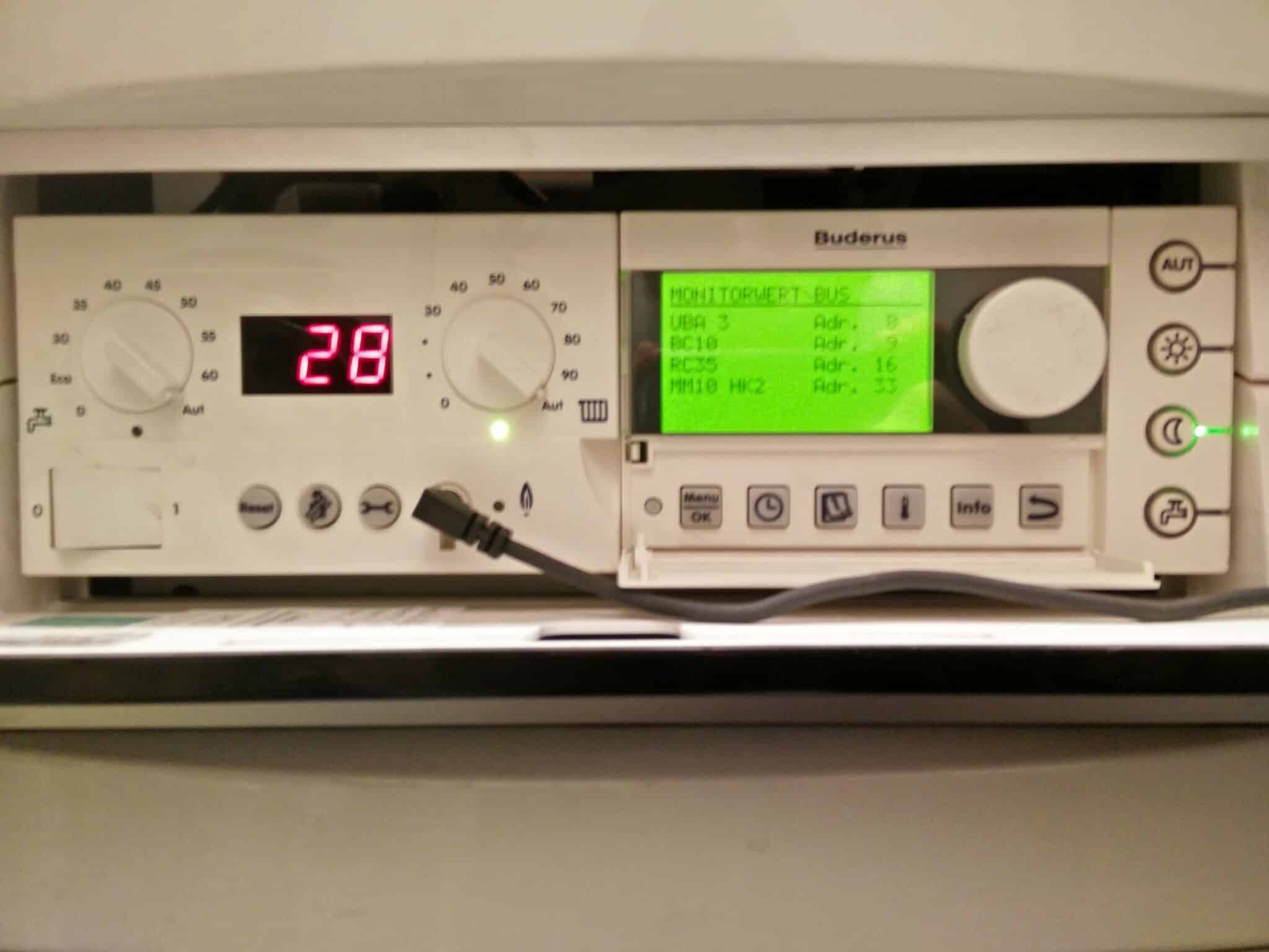
In the house where I am currently living there is an old Buderus boiler. The installation is managed with a RC 35 Room Controller and a MC10 + BC10 Basic Controllers placed inside the boiler room. Due to their situation, the room temperature measurement cannot be used to adjust the heating level. For this reason, the reference temperature used by the system to heat the house is an outside sensor. This method, called by Buderus weather-compensated control, was supposed to calculate the flow temperature in accordance with a heating curve configured. However, after the first winter living in the house went by, I noticed that controlling the house’s temperature was not easy.
For this reason I started to search for ways to control the boiler remotely. Luckily, Buderus boilers use a partially-documented protocol to communicate the controllers with the heating modules. I have divided this tutorial in three parts. In the current post I will summarize the existing information regarding the EMS Bus protocol. In this second entry, the Arduino controller developed to manage via WiFi the boiler is presented. Finally, you will find in this page the steps followed to integrate and import the boiler information in weeWx.
The EMS Bus
Many Buderus heating systems use the EMS (Energy Management System) Bus to exchange information between its components. You may also find it in products from Nefit, a company of the same group. To know if your installation is compatible with this tutorial, look at your room controller. Models RC20, RC25, RC30 and RC35 are connected using EMS.
The EMS bus supplies a voltage of 12 volts to power the controllers. Information travels at 9600 bauds and is coded using an 8N1 configuration, which means eight (8) data bits, no (N) parity bit, and one (1) stop bit. Therefore, for each byte, 10 bits will be sent: one start bit, the eight data bits, and the one stop bit.
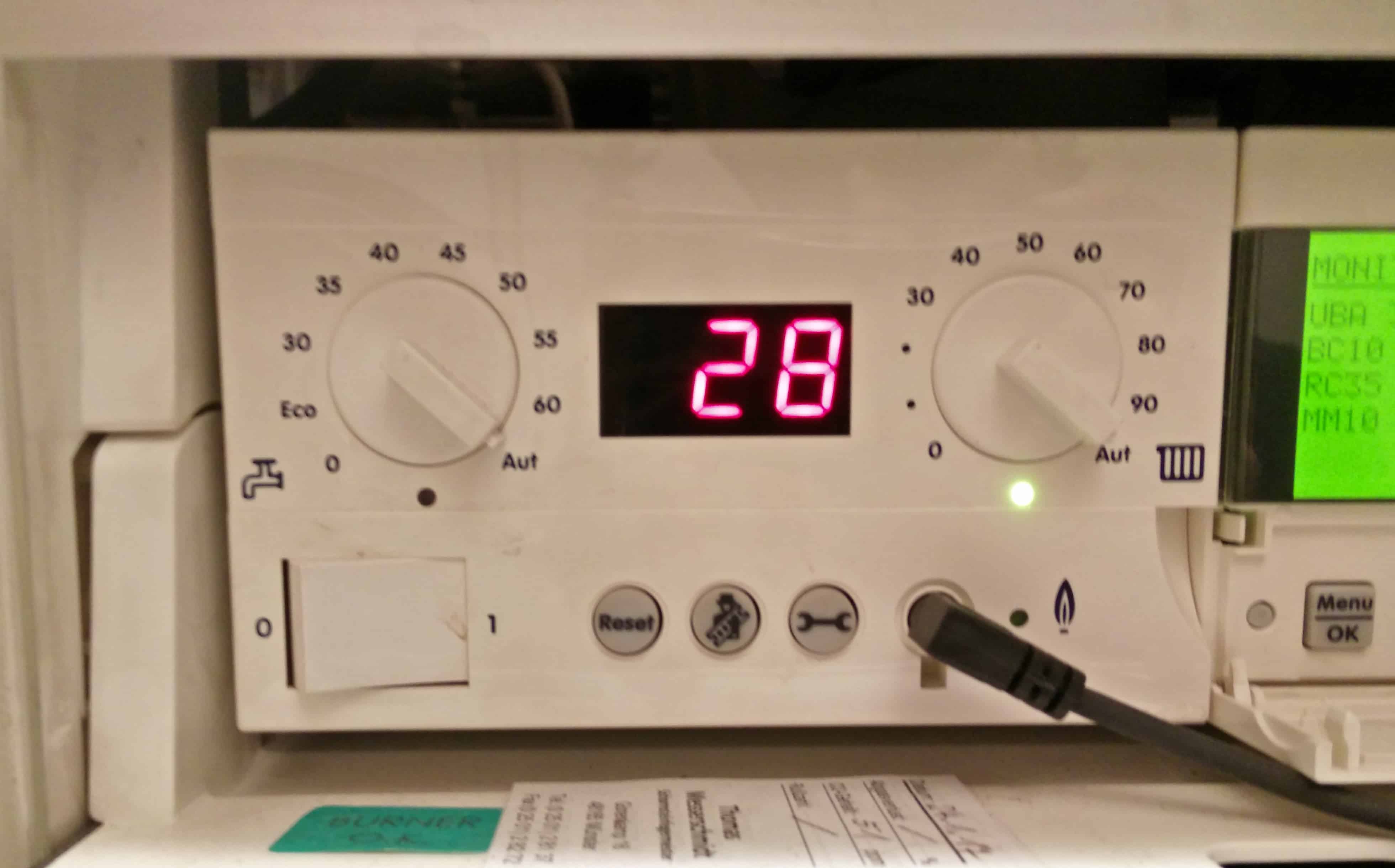
The EMS bus is usually accessible though a 3,5 mm service jack located in the front panel of the boiler. In my case, the jack plug was protected under a tap in the BC10.
The pinout of this service jack is as follows:
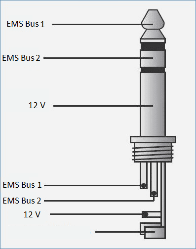
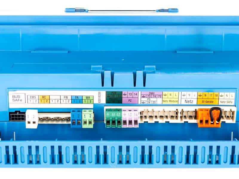
Apart from the jack, you will also find an EMS bus connection in the inside interface of the boiler. The exact location of these clamps will depend on your installation.

All the devices are connected in parallel to the bus. To manage the concurrent access there is a bus master, in this case the MC10 Basic Controller (also known as UBA 3). The bus master polls continuously to the rest of devices. If a device wants to access to the bus, he waits until being polled. Then it has approximately 200 ms to send its data package until his turn passes. This data package can be addressed to a third device of the bus, which will answer the request immediately. Each data package sent is ended with a break, an 11-bit long “zero” written in the bus. The bus master then will repeat every byte sent on the bus as an echo.
EMS Bus addresses
To allow addressing each bus participant has its own identification. All the existing addresses are queried once in a while by the bus master. When a device answers a poll, it is more frequently polled and is displayed on the RC35 screen with its designation as a bus subscriber.
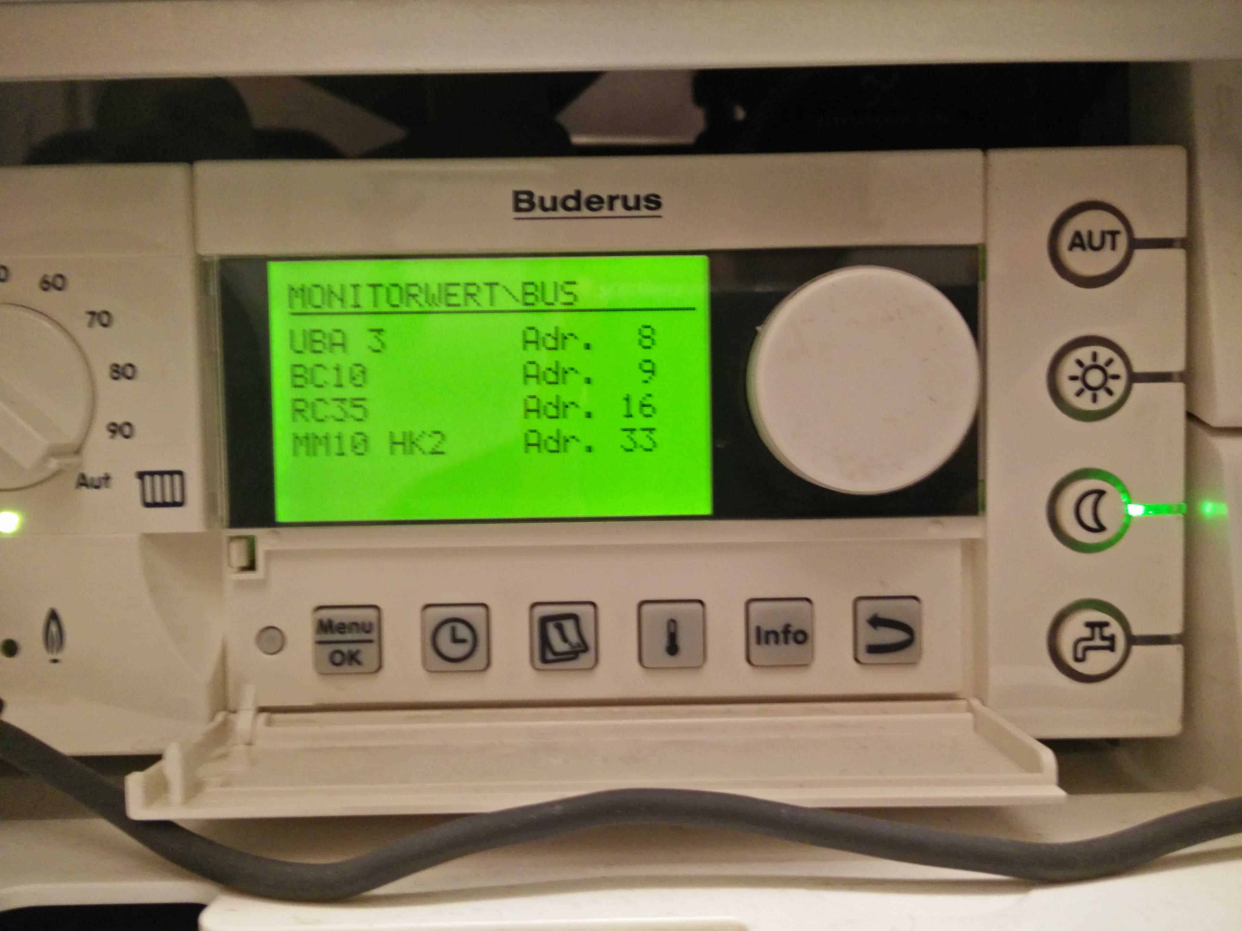
In the following table I summed up the most important bus addresses. To control the heater, the arduino connected to the EMS Bus will simulate the Buderus Service Key using the Address 0x0B.
| Address (hexadecimal) | Name in RC35 monitor display |
| 0x08 | MC10/UBA 3 |
| 0x09 | BC10 |
| 0x0B | Computer – Service Key |
| 0x10 | RC30 / RC35 |
| 0x11 | WM10 |
| 0x17 | RC20 |
| 0x21 | MM10 |
EMS Bus datagrams
A datagram with n Bytes send through the EMS bus follows this structure:
| Byte 0 | Byte 1 | Byte 2 | Byte 3 | Byte 4 to n-3 | Byte n-2 | Byte n-1 |
| Transmitter ID | Destination ID | Message Type | Offset | Data | CRC | Break |
- The first two bytes are the Transmitter and Receiver ID. Those are the addresses of the devices exposed in previous section. If the data package sent is a poll (read command), the receiver address’ higher byte should be set to 1 (masked with 0x80).
- The Message Type is a code representing a certain read or write operation. Each operation type has a specific payload (data) with the needed information encoded. In the next subsections the most common message types will be described.
- The Offset references a specific position in the payload. Since the payload starts in byte 4, offset 0 addresses the fourth byte in the datagram. To convert from real position in datagram to offset value, just rest to the original value 4. Offset is useful when sending write commands to change an specific configuration. In read commands use the offset to read only an specific byte of the datagram. If you are interested in the whole package, leave it to zero.
- The Data bytes represent the real information exchanged between the devices in the bus. Each message type has its own data structure and codification, so you will have to look at the specific message detail subsection to know how to code/decode the bytes exchanged. In read commands this field contains the longitude of the datagram requested.
- The CRC is a cyclic redundancy check performed over the first n-2 bytes. The CRC is calculated by the transmitter and attached to the datagram. The receiver compares its check value with one freshly calculated from the data block read. In case the CRC values do no match, the datagram contains an error and is therefore discarded.
- Finally the Break is a special code of 8 zero bites that indicates the end of the datagram.
Our arduino device connected to the EMS bus will send basically two types of datagrams:
- Read Commands – Some datagrams, such as the fast or the hot water monitor, are periodically sent and can be received by anybody connected to the EMS bus. Other types are only sent upon request. It means that, in order to receive an specific information, your arduino will have first to send a Read Command asking directly (poll) to the destination device about the message type. Apart from the message type, the offset and the length of the data requested will also be included in the data sent. The destination which will respond with an Answer Datagram containing the information inquired immediately. As it has been already commented, when polling the higher byte of the destination address is set to 1.
- Write Commands – These datagram types are sent to change some configuration in the destination device. In this situation the offset value is very relevant, because it will point the value in the payload structure being modified. Each value will have its own encoding, according to the message type. If the command is successfully received and executed, the destination device will send an Answer Datagram containing
0x01in its first position.
Note: There are more data types than the ones showed here, and I did not decode all the information provided for each message. I have focused my work on the most interesting parameters to be showed and controlled in a domotic system. Have a look at the references to find a more complete specification.
0x06 – RC Datetime
This message type contains the system date and time stored in the room controller (RC35). It is only sent upon demand. So, to know the time configured in the system you should send a read command (poll) first. There is no way to set this value with a write command (or at least I have not been able to achieve this so far).
The read command datagram (poll) has the following structure:
| Byte 0 | Byte 1 | Byte 2 | Byte 3 | Byte 4 | Byte 5 | Byte 6 |
| 0x0B | 0x10|0x80=0x90 | 0x06 | 0x00 | 0x08 | CRC | 0x00 |
Notes:
0xare hexadecimal values.- Byte 4 is the total longitude of the datagram 0x06: 8 bytes (from byte 4 to byte 11).
The answer datagram will contain the following information:
| Byte | Value | Comments |
| 0 | 0x10 | Transmitter ID |
| 1 | 0x0B | Destination ID |
| 2 | 0x06 | Message Type |
| 3 | 0x00 | Offset |
| 4 | Year | Last 2 digits of the current year (sum 2000) |
| 5 | Month | |
| 6 | Hour | |
| 7 | Day | |
| 8 | Minute | |
| 9 | Second | |
| 10 | Week day | 0 = Monday, .. , 6 = Sunday |
| 12 | CRC | |
| 13 | 0x00 |
Note: Byte 11 contains additional information, out of the scope of this project.
If you are interested only in the hour of the system, you can use the offset as shown in this read command:
| Byte 0 | Byte 1 | Byte 2 | Byte 3 | Byte 4 | Byte 5 | Byte 6 |
| 0x0B | 0x10|0x80=0x90 | 0x06 | 6 – 4 = 0x02 | 0x01 | CRC | 0x00 |
Notes:
- The hour is in byte 6 of the datagram 0x06. As the payload start in byte 4, to point this data the offset should be set to 6 – 4 = 2 (0x02).
- Byte 4 is the longitude of the data that we are interested in. In this case, 1 byte (0x01).
0x14 – UBA Working Time
This datagram contains the system total operating minutes. To ask for this information, the arduino should send the following read command datagram:
| Byte 0 | Byte 1 | Byte 2 | Byte 3 | Byte 4 | Byte 5 | Byte 6 |
| 0x0B | 0x08|0x80=0x88 | 0x14 | 0x00 | 0x03 | CRC | 0x00 |
The answer datagram will contain:
| Byte | Value | Comments |
| 0 | 0x08 | Transmitter ID |
| 1 | 0x0B | Destination ID |
| 2 | 0x14 | Message Type |
| 3 | 0x00 | Offset |
| 4-5-6 | System total operating time in minutes | Unsigned int with 24 bits (Big Endian order) |
| 7 | CRC | |
| 8 | 0x00 |
Note that if not otherwise indicated, all the values are transmitted using big endian order (the most significant bytes are located at the lowest storage address).
0x18 – UBA Monitor Fast
This is a status message containing some general information about the working conditions of the system. The boiler controller (MC10 Basic Controller) will send it periodically. However, it can also be requested.
If you don’t want to wait for the next package, your arduino should send the following read command:
| Byte 0 | Byte 1 | Byte 2 | Byte 3 | Byte 4 | Byte 5 | Byte 6 |
| 0x0B | 0x08|0x80=0x88 | 0x18 | 0x00 | 0x1B | CRC | 0x00 |
The answer datagram will follow this structure:
| Byte(s) | Bit | Value | Unit | Comments |
| 0 | 0x08 | Transmitter ID | ||
| 1 | 0x0B | Destination ID | ||
| 2 | 0x18 | Message Type | ||
| 3 | 0 | Offset | ||
| 4 | Selected Flow Temperature | ℃ | Flow temperature objective | |
| 5-6 | Current Flow Temperature | ℃ | Flow temperature measured multiplied by 10 | |
| 7 | Selected Burning Power | % | Burning power objective | |
| 8 | Current Burning Power | % | Burning power measured | |
| 11 | 0 | Burning Gas? | Yes/No | Flame |
| 11 | 2 | Fan Working? | Yes/No | |
| 11 | 3 | Ignition? | Yes/No | |
| 11 | 5 | Heating Pump Working? | Yes/No | |
| 11 | 6 | DHW Heating? | Yes/No | Domestic hot water heating |
| 11 | 7 | DHW Circuling? | Yes/No | Domestic hot water circulating |
| 17-18 | Current Flow Return Temperature | ℃ | Measured flow return temperature multiplied by 10 | |
| 19-20 | Flame current | mA | Flame current multiplied by 10 | |
| 21 | System Pressure | bar | System Pressure measured multiplied by 10 | |
| 22-23 | Service code | Two ASCII bytes encoding current system status | ||
| 24-25 | Error code | Code identifying the fault detected | ||
| 31 | CRC | |||
| 32 | 0x00 |
Notes:
- The Flow temperature objective cannot be directly set and is calculated according to the external and/or internal temperature, as well as the heating curve configured in the system. To know more how this value is obtained see the RC35 Installation and Servicing Instructions.
- Some values, such as the Current Flow Temperature or the Flame current are measured with a +/-0,1 precision. To avoid complicated float encoding, the value is sent multiplied by 10. To obtain its original value you will only have to divide it by 10.
- The most common service and error codes can be checked in the service instructions. If everything works correctly the status received will be 0Y-204 (selected flow temperature is higher than current flow) or 0H-203 (The device is ready for operation. There is no heating demand). In this web (in German) you can find the meaning of all the status and error codes.
0x19 – UBA Monitor Slow
This status message contains specific information about the system. It will only be sent upon request when the following read command is sent:
| Byte 0 | Byte 1 | Byte 2 | Byte 3 | Byte 4 | Byte 5 | Byte 6 |
| 0x0B | 0x08|0x80=0x88 | 0x19 | 0x00 | 0x19 | CRC | 0x00 |
The answer datagram will follow this structure:
| Byte(s) | Value | Unit | Comments |
| 0 | 0x08 | Transmitter ID | |
| 1 | 0x0B | Destination ID | |
| 2 | 0x19 | Message Type | |
| 3 | 0x00 | Offset | |
| 4-5 | External Temperature | ℃ | Outside temperature measured multiplied by 10 |
| 6-7 | Boiler Current Temperature | ℃ | Temperature measured in the boiler multiplied by 10 |
| 13 | Pump Modulation DHW | % | |
| 14-15-16 | Burner Start Counter | ||
| 17-18-19 | Burner Working Minutes | Minutes that the burner has been on | |
| 23-24-25 | Heating Working Minutes | Minutes that the heating has been on | |
| 29 | CRC | ||
| 30 | 0x00 |
0x33 – UBA Parameter Hot Water
This package type contains configuration information regarding the DHW (Domestic Hot Water). To obtain it, send the following read command:
| Byte 0 | Byte 1 | Byte 2 | Byte 3 | Byte 4 | Byte 5 | Byte 6 |
| 0x0B | 0x08|0x80=0x88 | 0x33 | 0x00 | 0x0B | CRC | 0x00 |
The answer datagram will follow this structure:
| Byte(s) | Value | Unit | Comments |
| 0 | 0x08 | Transmitter ID | |
| 1 | 0x0B | Destination ID | |
| 2 | 0x33 | Message Type | |
| 3 | 0x00 | Offset | |
| 6 | Hot Water Desired Temperature | ℃ | |
| 12 | Thermal Disinfection Temperature | ℃ | |
| 15 | CRC | ||
| 16 | 0x00 |
Note: Thermal Disinfection Function heats DHW to a temperature sufficient to kill pathogens (e.g. legionella).
It can be useful to modify one of the parameters of this last datagram. For instance, the hot water desired temperature is a typical value that you will want to control remotely from your domotic system. To change this value, just send this write command:
| Byte(s) | Value | Unit | Comments |
| 0 | 0x0B | Transmitter ID | |
| 1 | 0x08 | Destination ID | |
| 2 | 0x33 | Message Type | |
| 3 | 0x02 | Offset: 6 – 4 = 2 | |
| 4 | Hot Water Desired Temperature | ℃ | Max value is 80℃ |
| 5 | CRC | ||
| 6 | 0x00 |
Note: As commented previously, the offset references a specific position in the datagram payload. In the previous answer table you can see that the Hot Water Desired Temperature parameter occupies byte 6. As the payload starts in byte 4, to edit this temperature the offset should be set to 6 – 4 = 2.
Once this write command is sent, if the operation is successfully processed by the destination device, it will send an acknowledge message containing only one byte: 0x01.
0x34 – UBA Monitor Hot Water
It consists of an status message containing specific information about the working conditions of the hot water system. To request this data package, use the following read command:
| Byte 0 | Byte 1 | Byte 2 | Byte 3 | Byte 4 | Byte 5 | Byte 6 |
| 0x0B | 0x08|0x80=0x88 | 0x34 | 0x00 | 0x10 | CRC | 0x00 |
The answer datagram will follow this structure:
| Byte(s) | Bit | Value | Unit | Comments |
| 0 | 0x08 | Transmitter ID | ||
| 1 | 0x0B | Destination ID | ||
| 2 | 0x34 | Message Type | ||
| 3 | 0x00 | Offset | ||
| 4 | Selected DHW Temperature | ℃ | DHW temperature objective | |
| 5-6 | Current DHW Temperature | ℃ | DHW temperature measured multiplied by 10 | |
| 9 | 0 | Day Mode DHW | Yes/No | DHW Program in day mode? |
| 9 | 1 | DHW Once | Yes/No | Extra DHW activated? |
| 9 | 2 | Thermal Disinfection DHW | Yes/No | Is thermal disinfection running? |
| 9 | 3 | Prepare DHW | Yes/No | Heating DHW? |
| 14-15-16 | DHW Working Minutes | |||
| 17-18-19 | DHW Start Counter | |||
| 20 | CRC | |||
| 21 | 0x00 |
Notes:
- When the boiler is heating DHW, the Selected Hot Water Temperature is also contained in datagram 0x33 – UBA Parameter Hot Water. Maximal / Minimal temperature are 70℃ / 30℃
- The DHW Once is a functionality to heat up an extra quantity of water. To save energy, during day mode DHW is only reheated automatically when its temperature falls 5 °C below the set DHW temperature. If large amounts of hot water are needed outside the set times for day mode, this function heats up DHW once. This bit indicates if the function has been activated or not.
0x35 – Flags Hot Water
This datagram is used to remotely activate the DHW Once functionality. Therefore, it is only used as a write command:
| Byte(s) | Value | Unit | Comments |
| 0 | 0x0B | Transmitter ID | |
| 1 | 0x08 | Destination ID | |
| 2 | 0x33 | Message Type | |
| 3 | 0x00 | Offset: 4 – 4 = 0 | |
| 4 | DHW Once | Decimal | 39 = start, 7 = stop |
| 5 | CRC | ||
| 6 | 0x00 |
Note: The DHW Once functionality should be, theoretically, activated by means of this data package. According to the EMS Wiki, when the value in byte 4 is greater than 35, the function is started. When the value is 3, the function is stopped. However, I have noticed that sometimes this values are directly ignored despite receiving an acknowledge datagram from the bus master. After some try and error, I have found that, for the RC35 Room Controller, values 39 and 7 (for activation and deactivation) work better. The current status of the function can be checked in parameter DHW Once of datagram 0x34 – UBA Monitor Hot Water.
0x37 – Working Mode Hot Water
This package type contains configuration options regarding the working mode of the DHW system. To obtain this datagram, send the following read command:
| Byte 0 | Byte 1 | Byte 2 | Byte 3 | Byte 4 | Byte 5 | Byte 6 |
| 0x0B | 0x10|0x80=0x90 | 0x37 | 0x00 | 0x0A | CRC | 0x00 |
The answer datagram will follow this structure:
| Byte(s) | Value | Unit | Comments |
| 0 | 0x10 | Transmitter ID | |
| 1 | 0x0B | Destination ID | |
| 2 | 0x37 | Message Type | |
| 3 | 0x00 | Offset | |
| 4 | DHW Program | 0 = Heating Program, 255 = Own Program | |
| 5 | DHW Circulation Pump Program | 0 = Heating Program, 255 = Own Program | |
| 6 | DHW Working Mode | 0 = Off, 1 = On, 2 = Auto | |
| 7 | DHW Circulation Pump Working Mode | 0 = Off, 1 = On, 2 = Auto | |
| 8 | Thermal Disinfection | 0 = Off , 255 = On | |
| 9 | Thermal Disinfection Week Day | 0..6 = Monday to Sunday. 7 = Everyday | |
| 10 | Thermal Disinfection Hour | 0..24 | |
| 14 | CRC | ||
| 15 | 0x00 |
Notes:
- The DHW can heat up (and pump) water according to its own program or following the heating one.
- The DHW (and his pump) can be configured to serve hot water always (mode on), never (mode off), or following the configured program (mode auto).
The parameters of the previous datagram are fully configurable. For instance, when leaving the house for holidays, you can switch the DHW working mode to off. To change this value, just send the following write command:
| Byte(s) | Value | Unit | Comments |
| 0 | 0x0B | Transmitter ID | |
| 1 | 0x08 | Destination ID | |
| 2 | 0x37 | Message Type | |
| 3 | 0x02 | Offset: 6 – 4 = 2 | |
| 4 | 0x00 | 0 = Off, 1 = On, 2 = Auto | |
| 5 | CRC | ||
| 6 | 0x00 |
Once sent, if the operation is successfully processed by the destination device, it will send an acknowledge message containing only one byte: 0x01.
0x3D – Working Mode Heating Circuit 1
This package is used to configure in the RC35 room controller the working mode of the Heating Circuit 1 (HC1). If your installation has more than one circuit, you should use the packages 0x47 (HC2), ox51 (HC3) or 0x5B (HC4).
To obtain this datagram, send the following read command:
| Byte 0 | Byte 1 | Byte 2 | Byte 3 | Byte 4 | Byte 5 | Byte 6 |
| 0x0B | 0x10|0x80=0x90 | 0x3D | 0x00 | 0x2A | CRC | 0x00 |
The answer datagram will follow this structure:
| Byte(s) | Value | Unit | Comments |
| 0 | 0x10 | Transmitter ID | |
| 1 | 0x0B | Destination ID | |
| 2 | 0x3D | Message Type | |
| 3 | 0 | Offset | |
| 5 | Selected Night Temperature | ℃ | Desired temperature multiplied by 2 |
| 6 | Selected Day Temperature | ℃ | Desired temperature multiplied by 2 |
| 7 | Selected Holiday Temperature | ℃ | Desired temperature multiplied by 2 |
| 8 | Room Temperature Influence | ℃ | Temperature influence multiplied by 2 |
| 10 | Room Temperature Offset | ℃ | Temperature offset multiplied by 2 |
| 11 | HC1 Working Mode | 0 = Night, 1 = Day, 2 = Auto | |
| 26 | Summer/Winter threshold | ℃ | Switchover temperature threshold for summer/winter mode |
| 29 | Night Setback | 0 = Shutdown, 1 = Reduced Operation, 2 = Room Setback, 3 = Outdoor Setback | |
| 43 | Temperature threshold for outdoor setback | Only with Outdoor Setback activated. Switch between shutdown and reduced operation. | |
| 46 | CRC | ||
| 47 | 0x00 |
Notes:
- The temperatures contained in this datagram type have a precision of +/- 0,5 degrees. Maximal / Minimal temperature are 29℃ / 6℃. To avoid using float types, they are presented multiplied by 2. To recover the original value, just multiply the obtained value by 2.
- The Room Temperature Influence parameter is used to determine whether and to what extent the room temperature should influence the heating characteristics. If the RC35 unit is installed in a room, the greater the parameter set, the greater the influence of the room temperature on the heating characteristics. Set it to 0 to control the heating characteristics solely by outside temperature. Set only when the weather-compensated control mode is activated.
- The Room Temperature Offset shifts left and right the heating characteristic curve. Bigger offsets are equivalent to increasing the target room temperature, while lower offsets reduces the target room temperature. Set only when the weather-compensated control mode is activated.
- The Night Setback mode controls the reduction mode applied at night. Shutdown will switch off the boiler and the heating circuit pump, activating the frost protection. Reduced Operation uses the target room temperature for nighttime setted to keep heating (the heating circuit pump runs constantly). Room Setback uses the room temperature (activate only if the RC35 is installed in a room) to jump between reduced operation mode and shutdown, depending on the target night temperature set. Outdoor Setback works in a similar way as room setback, using the external temperature to switch between shutdown and reduced mode, depending on the temperature threshold for outdoor setback.
- Watchout with the size of this EMS Datagram. Arduino’s serial transmission buffer size is limited (defined in the library) and usually will not be long enough to capture this whole datagram. Moreover, I have not been able to capture without error a dataframe with more than 32 bytes. I have read in Mikrocontroller.net forums that maximum size varies depending on thermostat firmware version. To avoid loosing bytes, datagrams longer than 32 bytes will be split in different commands.
These parameters are, as previous ones, fully configurable. For instance, to set the working mode to day in the HC1 just send this write command:
| Byte(s) | Value | Unit | Comments |
| 0 | 0x0B | Transmitter ID | |
| 1 | 0x10 | Destination ID | |
| 2 | 0x3D | Message Type | |
| 3 | 0x07 | Offset: 11 – 4 = 7 | |
| 4 | 0x01 | 0 = Night , 1 = Day , 2 = Auto | |
| 5 | CRC | ||
| 6 | 0x00 |
Or to change the night temperature to 18,5 ℃, use this write command:
| Byte(s) | Value | Unit | Comments |
| 0 | 0x0B | Transmitter ID | |
| 1 | 0x10 | Destination ID | |
| 2 | 0x3D | Message Type | |
| 3 | 0x01 | Offset: 5 – 4 = 1 | |
| 4 | 0x25 | ℃ | 18,5 * 2 = 37 |
| 5 | CRC | ||
| 6 | 0x00 |
As usual, if the operation is successfully processed, an acknowledge message ( 0x01) will be sent.
0x3E – Monitor Heating Circuit 1
This data package contains status information about the Heating Circuit 1 (HC1). Use 0x48 for HC2, 0x52 for HC3 and 0x5C for HC4. To request this data package, use the following read command:
| Byte 0 | Byte 1 | Byte 2 | Byte 3 | Byte 4 | Byte 5 | Byte 6 |
| 0x0B | 0x10|0x80=0x90 | 0x3E | 0x00 | 0x10 | CRC | 0x00 |
The answer datagram will follow this structure:
| Byte(s) | Bit | Value | Unit | Comments |
| 0 | 0x08 | Transmitter ID | ||
| 1 | 0x10 | Destination ID | ||
| 2 | 0x3E | Message Type | ||
| 3 | 0 | Offset | ||
| 4 | 5 | Holiday Mode | Yes/No | |
| 5 | 0 | Summer Mode | Yes/No | |
| 5 | 1 | Day Mode | Yes/No | |
| 5 | 7 | Pause Mode | Yes/No | |
| 6 | Desired Room Temperature | ℃ | Desired temperature multiplied by 2 | |
| 20 | CRC | |||
| 21 | 0x00 |
Note: This data package is only a monitor of the heating circuit status. To modify the values, use the Working Mode datagrams.
0x3F – Switching Program Heating Circuit 1
This package is used to configure the switching program of the RC35 room controller for the Heating Circuit 1 (HC1). The switching points defined will be used in the automatic mode to changeover between day and night mode at defined times.
Besides the default programs already defined in the controller, the user can create and edit two fully configurable programs with 42 switching points each per Heating Circuit. Moreover, there is also a user defined program for the DHW and the DHW pump. They all use the same datagram structure, changing only the message type as shown in this table:
| Component | Message Type |
| DHW | 0x38 |
| DHW Pump | 0x39 |
| HC1 – User Program 1 | 0x3F |
| HC1 – User Program 2 | 0x42 |
| HC2 – User Program 1 | 0x49 |
| HC2 – User Program 2 | 0x4C |
| HC3 – User Program 1 | 0x53 |
| HC3 – User Program 2 | 0x56 |
| HC4 – User Program 1 | 0x5D |
| HC4 – User Program 2 | 0x60 |
To obtain one of these datagrams, send the following read command:
| Byte 0 | Byte 1 | Byte 2 | Byte 3 | Byte 4 | Byte 5 | Byte 6 |
| 0x0B | 0x10|0x80=0x90 | 0x3F | 0x00 | 0x63 | CRC | 0x00 |
The answer datagram will follow this structure:
| Byte(s) | Value | Comments |
| 0 | 0x10 | Transmitter ID |
| 1 | 0x0B | Destination ID |
| 2 | 0x3F | Message Type |
| 3 | 0x00 | Offset |
| 4/5 | Switch Point 0 | See the notes |
| 6/7 | Switch Point 1 | See the notes |
| … | ||
| 86/87 | Switch Point 41 | See the notes |
| 88 | Program Name | 0x00 = User 1 0x01 = Family 0x02 = Morning 0x03 = Evening 0x04 = Midmorning 0x05 = Afternoon 0x06 = Midday 0x07 = Single 0x08 = Seniors 0x09 User2 |
| 89 | Pause Time | Start pause function (night mode) for the specified hours |
| 90 | Party Time | Start party function (day mode) for the specified hours |
| 91 | Start Holidays Day | |
| 92 | Start Holidays Month | |
| 93 | Start Holidays Year | Two last digits (sum 2000) |
| 94 | End Holidays Day | |
| 95 | End Holidays Month | |
| 96 | End Holidays Year | Two last digits (sum 2000) |
| 97 | Start Home Holidays Day | |
| 98 | Start Home Holidays Month | |
| 99 | Start Home Holidays Year | Two last digits (sum 2000) |
| 100 | End Home Holidays Day | |
| 101 | End Home Holidays Month | |
| 102 | End Home Holidays Year | Two last digits (sum 2000) |
| 103 | CRC | |
| 104 | 0x00 |
Notes:
- The switch points are two bytes coded following this structure: XXX00YYY – ZZZZZZZZ.
- The first 3 bits of the first byte (X) are the day of the week. Consider 0 = Monday, 1 = Tuesday, 2 = Wednesday, 3 = Thursday, 4 = Friday, 5 = Saturday, 6 = Sunday and 7 = Undefined.
- The last 3 bits of the first byte (Y) are the swtich action. Use 0 = Off, 1 = On and 7 = Undefined.
- The second byte (Z) is a point in time. Follow this code 00= 00:00, 01 = 00:10, …, 8F = 23:50, 90 = Undefined. To obtain the hour, get the integer part of the division Z * 10 / 60. The minute will be the rest (mod) of the division.
- If a Holiday period is configured, the system will run in reduced mode using the adjusted holiday temperature. If Home Holidays is defined, the system will run as Saturday during this period.
- Watchout with the size of this EMS Datagram. As previously commented, message size is limited by RC firmware version. Split the command to recieve the whole datagram.
- For each heating circuit can be set up to two users program, but only one holiday configuration. For this reason, only User Program 1 messages contain the whole datagram with 99 bytes. The User Program 2 messages contain only the 42 Switch Points (84 bytes).
In order to create a complete user program with different switch points you will have to send several write commands (one per each switch point). For example, this datagram will set Switch Point 5 in HC1 to start the day mode on Fridays.
| Byte(s) | Value | Unit | Comments |
| 0 | 0x0B | Transmitter ID | |
| 1 | 0x10 | Destination ID | |
| 2 | 0x3F | Message Type | |
| 3 | 0x0A | Offset: 14 – 4 = 10 | |
| 4 | 0xA1 | X: Friday = 5 = 101
Y: On = 001 101000001 = 161 = 0xA1 |
|
| 5 | CRC | ||
| 6 | 0x00 |
This second datagram will set the time of Switch Point 5 in HC1 at 7:20 am.
| Byte(s) | Value | Unit | Comments |
| 0 | 0x0B | Transmitter ID | |
| 1 | 0x10 | Destination ID | |
| 2 | 0x3F | Message Type | |
| 3 | 0x0B | Offset: 15 – 4 = 11 | |
| 4 | 0x2C | 7:20 = 7 * 6 + 2 = 44 = 0x2C | |
| 5 | CRC | ||
| 6 | 0x00 |
As usual, if the operation is successfully processed an acknowledge message will be sent.
0xAB – MM10 Monitor
This is a status message containing some information about the working conditions of the mixer. Of course, you should only send this datagram if there is an MM10 mixer in your system. To receive this data package, just send the following read command:
| Byte 0 | Byte 1 | Byte 2 | Byte 3 | Byte 4 | Byte 5 | Byte 6 |
| 0x0B | 0x21|0x80=0xA1 | 0xAB | 0x00 | 0x04 | CRC | 0x00 |
The answer datagram will follow this structure:
| Byte(s) | Bit | Value | Unit | Comments |
| 0 | 0x21 | Transmitter ID | ||
| 1 | 0x0B | Destination ID | ||
| 2 | 0xAB | Message Type | ||
| 3 | 0 | Offset | ||
| 4 | Selected Flow Mixer Temperature | ℃ | Flow temperature objective | |
| 5-6 | Current Flow Mixer Temperature | ℃ | Flow temperature measured multiplied by 10 | |
| 7 | Mixer Status | % | Mixer status | |
| 8 | CRC | |||
| 9 | 0x00 |
References
All this work is based in the information contained in this wiki (in German language). In case the web is not available, I have exported it as a PDF. Without this help, I would not have been able to decode the data packages sent through the EMS Bus.
Another very good source of information are the microcontroller forums, specially these topics: 1, 2 and 3.
Finally, to fully understand the working mode and options of the boiler I recommend you to have a look at the RC35_Installation_and_Servicing_Instructions as well as at the RC35 User Instructions.
Hi Dani, only just discovered this. Great work! As you know I did something similar for an ESP8266. I was wondering whether you manage to find a way to query the Thermostat and find out if its an RC20, RC30 or RC35? I think it may be type 0x01 but not sure.
Hi Paul,
I think you can use message type 0x3D – Working Mode Heating Circuit 1. Byte 30 is the controller type (0 – no controller, 1 – RC20, 2 – RC3x).
I don’t know if there is a way to differentiate between RC30 and 35, maybe you can ask for a telegram which has some data only sent by RC35 (like byte 20 of message type 0x3E) and if this byte is not sent, assume that the thermostat is a RC30.
I haven’t found information regarding message type 0x01, what does it do? Maybe with message 0x02 (sofware version) you can also infer the thermostat type.
Regards,
Dani
Hi Dani,
thanks for this great explanation. I myself am reading from the EMS bus according to my following project: http://www.kabza.de/MyHome/EMSbus.html
Thanks and best regards,
Alex
Thanks Alex,
Your web seems very interesting! You are only reading values from your boiler, aren’t you?
Regards,
Dani
Hi Dani,
correct, I´m just reading. But by the way, the “UBA Monitor Slow” message also comes periodically each minute, not only on request as you mentioned.
Thanks and take care,
Alex
“The bus master then will repeat every byte sent on the bus as an echo.”
Are you sure? As far I know, although it’s true that every transmitted byte is echoed, it’s done immediately just because how the modulating single signal line for both receive/transmit works. I’ve never observed that bus master is repeating anything after receiving complete datagram.
Nice work…enjoyed reading it! My beef is with a Buderus GB142/30 as it has a silly digital pressure sensor that is…..not beneficial as it dies occasionally and is costly to replace. Lately, I reverted to injecting my own digital info via a frequency generator and am able to trick the controller into thinking that life is good. However, it is a simple patch and what I really like to do is turn the darn thing off in the firmware. It is not needed as I have another, simpler external sensor that measures water temp (like an over temp sensor), water level and water pressure. So far, accessing the firmware is not successful. Would you have an idea, perhaps?
Are you trying to access the firmware from MCU of the boiler main controller? Have you success with it? What MCU is on the board?
I have downloaded the firmware from Buderus RC35 regulator, but unfortunately I don’t have other hardware to experiment with. I’d like to have spare BC10 (main controller of GB172 boiler), but those are quite expensive.
BTW, I’m documenting some of RC35 internals here:
https://github.com/gashtaan/buderus-rc35-internals