Contents
Introduction
Years ago I started doing some tests to control a Roomba remotely using an Arduino One with a RN-VX WiFly module. Last month I decided to revitalize the idea but with a new objective: to turn the Roomba into a surveillance robot with the ability to take photos and videos. The first idea was to keep using the Arduino as microcontroller employing an Arducam module to capture pictures. However I quickly found that the image processing capacity of Arduino was too limited for my interests. The second option was to change the platform and use a Raspberry Pi Zero W with a camera module. This alternative meant some challenges, specially regarding powering but also offered more possibilities. In this post I will explain how to build Roomberry, a surveillance robot based on Roomba using a Raspberry Pi Zero W and a camera module.
A demonstration of Roomberry’s capabilities and the web interface developed to interact with it can be seen in the following video.
iRobot Roomba
iRobot’s Roomba offers an Open Interface (OI) to interact with the robot though a mini DIN connector. The OI is a software interface designed for Roomba creator 2 (an adaptation of serie 600). However, it is fully compatible with series 500 and 700 too. There are nevertheless some bugs depending on the platform and the firmware version used. The software interface lets you manipulate Roomba’s behaviour and read its sensors. A full description of its capabilities can be found in this document.
Mini DIN connector
The Roomba mini DIN connector is located in the front right side of Roomba serie 700 and has 7 pins. Its position varies slightly in the series 600, whose location is in the rear right side of Roomba, under a snap-away plastic guard. Mini DIN 7 male connectors are complicated to buy, however the more common mini DIN 8 pin male connector is also compatible. 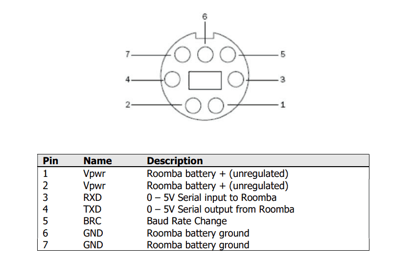
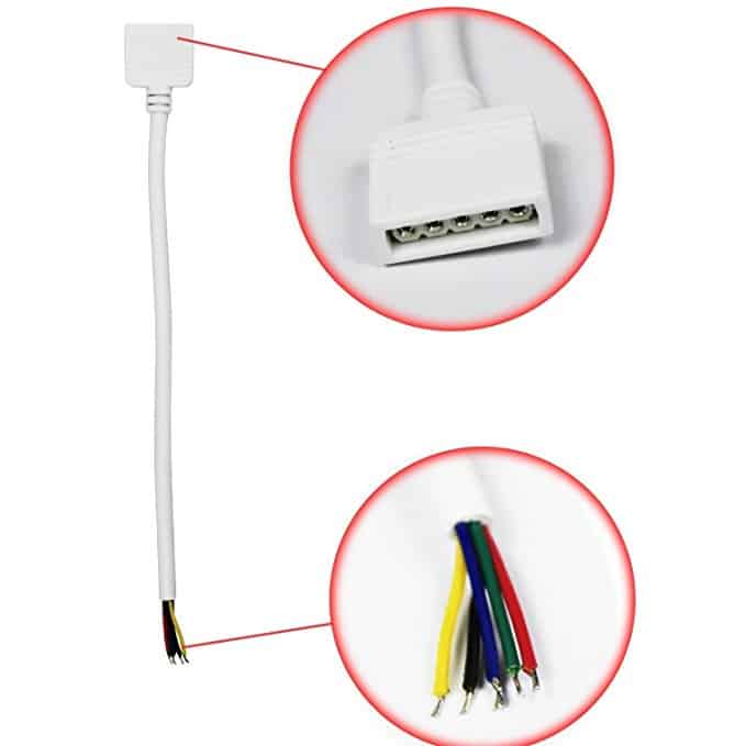
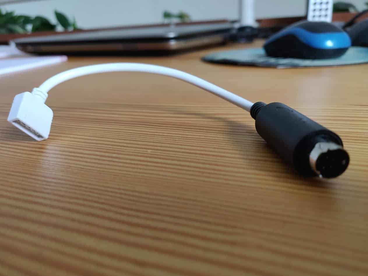
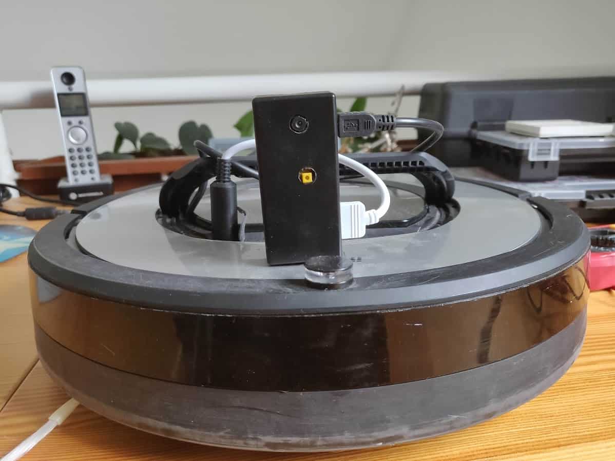
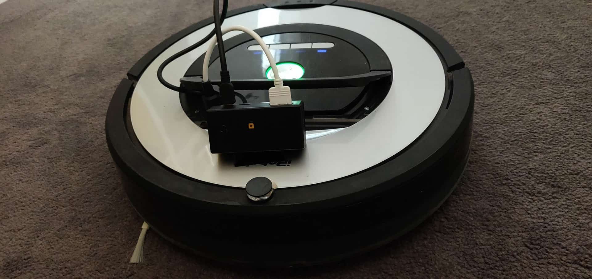
To ensure a smooth and reliable connection/disconnection of the port, I soldered a 5 pin cable (designed for LED strips) with a female connector to a mini DIN 8 pin male connector using pins 1-2 (power), 6-7 (ground), 3 (RxD), 4 (TxD) and 5 (BRC). However, as commented later on, the power/ground connection were finally not needed. The resulting cable can be seen in the following pictures.
 |
 |
|---|
Roomba Serial Port
To use the OI, the commands should be sent though a two-way serial communication created in mini DIN 7 pins 3 (RxD) and 4 (TxD). This UART port works at TTL levels (0 – 5 V). This voltage is perfectly fine for microcontrollers using 5V logic, like most Arduino boards. However it is not good for those with lower voltage logic levels (like the Raspberry Pi).
In theory, pin 3 (RxD) will take 3.3 V as the high logic level. But the Roomba will output 5V on its pin 4 (TxD), which may damage the Raspberry Pi Zero. To keep the hardware safe a logic level shifter should be used. The simplest way to do this is with a resistor divider, as already implemented in Calduino, but this may not work at high speeds (Roomba’ serial port works at 115200 bauds).
Instead of that, an active level shifter is preferable. If you want to build your own circuit, use the field effect transistor AN10441 as explained here. A much easier option is to use one of the existing bi-directional logic level converters such as this one from Adafruit. This device can manage up to 4 signals and safely step them down from 5V to 3.3V. At the same time it steps signals up from 3.3V to 5V .
Powering Raspberry Pi from Roomba
There are a few alternatives to provide power supply through Roomba’s battery:
Powering from the mini DIN 7
The mini DIN 7 provides an unregulated direct connection in pins 1/2 (Vcc) – 6/7 (Gnd) to Roomba’s battery. The connection is limited to 200 mA though a PTC resettable fuse. It offers a voltage between 20.5 and 10V, limited to 0.2A with a power of 2W. The continuous draw from these two pins together should not exceed 200 mA. Drawing a peak greater than 500 mA will reset the fuse.
A Raspberry Pi Zero W should be able to work using this supply. The Raspberry Pi Foundation rates the typical bare-board active current consumption in 150 mA. This benchmark places it between 120 mA in idle status and 180 mA under stress (playing FullHD video, for instance). However, here the extra consumption of the camera is not considered. According to my measurements, the camera (I use this one, with the same sensor as version 1 official Pi camera) increases the power consumption to more than 300 mA, with peaks of 450 mA. During my test the fuse was tripped several times while recording videos.
As a conclusion, the existing thermofuse dismisses the use of this connection to power the Raspberry Pi Zero W. I have not been able to find out if it is possible and safe to remove the fuse from the board without damaging other components.
Powering from an external power bank
There are a few alternatives to avoid this fuse limit. On the one hand, the easier solution would be to use a power bank to provide external power to the Raspberry Pi Zero. However, it will require the user to charge it periodically. Another option would be to design a serial connection between the mini DIN 7 power supply and the power bank. With a couple of electronic components it should be possible to use the Roomba battery to charge the power bank. To simplify my design I decided to avoid the use of any additional sources of power.
Powering from the battery
I finally decided to bypass the fuse by building a direct connection to the battery pack. The counterpart of this option is that you will have to partially disassemble the robot. In Roomba series 600 there are two big pads directly connected to the battery pack below the dock button. In Roomba series 700/800 you will have to disassemble a couple of components more. Have a look at the following video until minute 6 to see, step by step, how to access your robot’s motherboard. Once done, just solder a couple of cables to the battery pad as shown in next pictures.
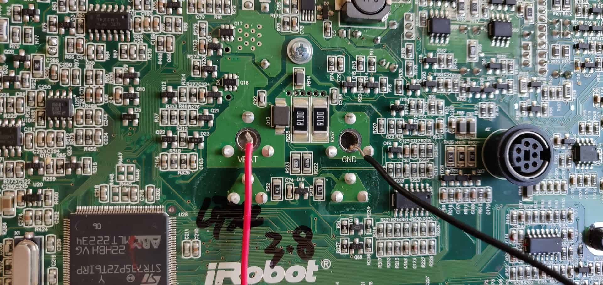
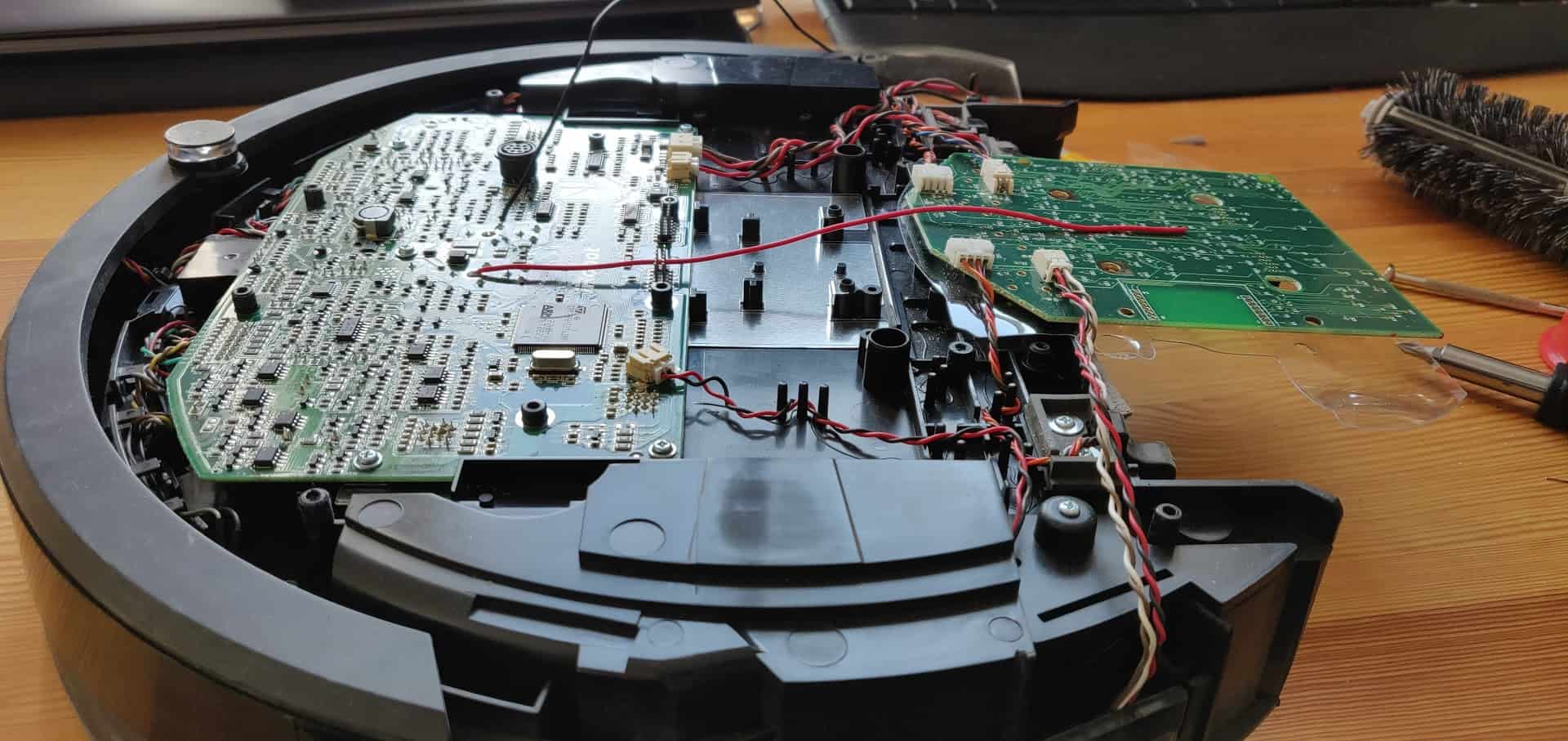
These cables will provide a direct connection to the battery not limited by any fuse. They supply between 20.5 and 10V, depending on the battery charging level. However, the Raspberry Pi Zero W needs a regulated 5 V source of power. To reduce the voltage an step down is used. There are a lot of options to do this ranging from the use of a cheap linear regulator (such as the 7805 TO-220) with a couple of capacitors to installing a switching regulator.
Due to its higher efficiency, and considering that it will be always connected, I would advise to use/buy a good quality (avoid China imitations) step-down switching regulator. I have used Pololu D24V5F5 buck regulator which takes an input of up to 36 V and reduces it to 5V for a maximum output current of 500 mA. Its efficiency is rated between 85% and 90% and has a very low dropout. You can also use an UBEC (Universal Battery Elimination Circuit), such as the one commonly used in RC world. I placed my voltage regulator in a free space situated in the centre – right side of the robot.

The connections were properly protected with heatshrink and the D24V5F5 module was covered with isolating plastic (I did not take any photos of this). I soldered the module output to a micro-USB cable, which allows me to connect it directly to the Raspberry Pi Zero W power input.
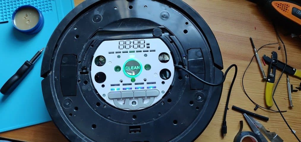
Using a rotating drilling tool and sandpaper I created a little notch in Roomba’s upper cover to allow a clean outlet of the micro USB cable as can be seen in the following picture.
Roomba OI modes
The Roomba OI has four operating modes: Off, Passive, Safe, and Full.

Off Mode
After a battery change or when first powered, the OI is in off mode. In this status the Roomba listens to the port at the default baud rate (115200) waiting for an
start command. The commands reset and stop can be sent at any time and will turn OI also in off mode.
Passive Mode
Once an Start command is sent, Roomba enters passive mode. In this status you can request and receive sensor data using any of the sensor commands. However you cannot change the current command parameters for the actuators (motors, speaker, lights, low side drivers, digital outputs). Roomba will enter passive mode too if one of the cleaning mode commands (Spot, Clean, Seek Dock, etc.) is sent.
While in passive mode Roomba will go into off mode after five minutes of inactivity to save power and preserve battery. According to iRobot documentation, sleep can be disabled just pulsing the BRC pin low periodically before these five minutes expire. Each pulse should reset this five minutes counter. In the tests that I have performed (with a Roomba 780), pulling low the BRC will only wake up the robot, but it will not prevent it from going to power saving mode. The robot will beep when it wakes up (if it is not being charged in the dock station).
Safe Mode
Roomba will enter in Safe mode if the Safe command is sent. Safe mode gives you full control of the robot and turns all motors and LEDs off. However, if a safety-related condition is not met, the robot will turn automatically into passive mode. Those safety conditions are: detection of a cliff while moving forward, wheel drop and charger connection. In this mode Roomba will not charge (although being at the dock) and will not save power by switching to off mode after 5 minutes of inactivity. This point is very important: you can end up draining the robot’s battery and damaging it if you don’t switch to passive or off mode.
Full Mode
When you send a Full command to the OI, Roomba enters Full mode. The robot will behave exactly as in Safe mode, but it will not consider the safety-related conditions previously commented so be aware of the risks!
Battery precautions
As commented, in Passive mode, Roomba will sleep after 5 minutes of inactivity to preserve battery power. In Safe and Full modes, Roomba will never sleep, and if it is left in this state for an extended period of time, it will deeply discharge its battery, even if plugged into the charger. The charger will power Roomba in all modes, but it will not charge the battery in Safe or Full mode. It is important to return Roomba to Passive or Off mode once a job is done and/or when battery level is low in order to protect it.
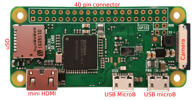
Raspberry Pi Zero W
The Raspberry Pi Zero W is an updated version of the Raspberry Pi Zero with wireless LAN and Bluetooth. The model includes a 1 GHz single-core CPU, 512MB of RAM, mini-HDMI, a micro-USB OTG port, micro-USB for power, 40-pin header, composite video, reset headers, a camera connector, as well as the new wireless features. It uses wireless chip Cypress CYW43438 that supports 802.11b/g/n Wi-Fi (2.4GHz-only) and Bluetooth 4.0 (same chip as Raspberry Pi 3 Model B). I bought it in Pimoroni with headers (not soldered) and adapters for 16€.
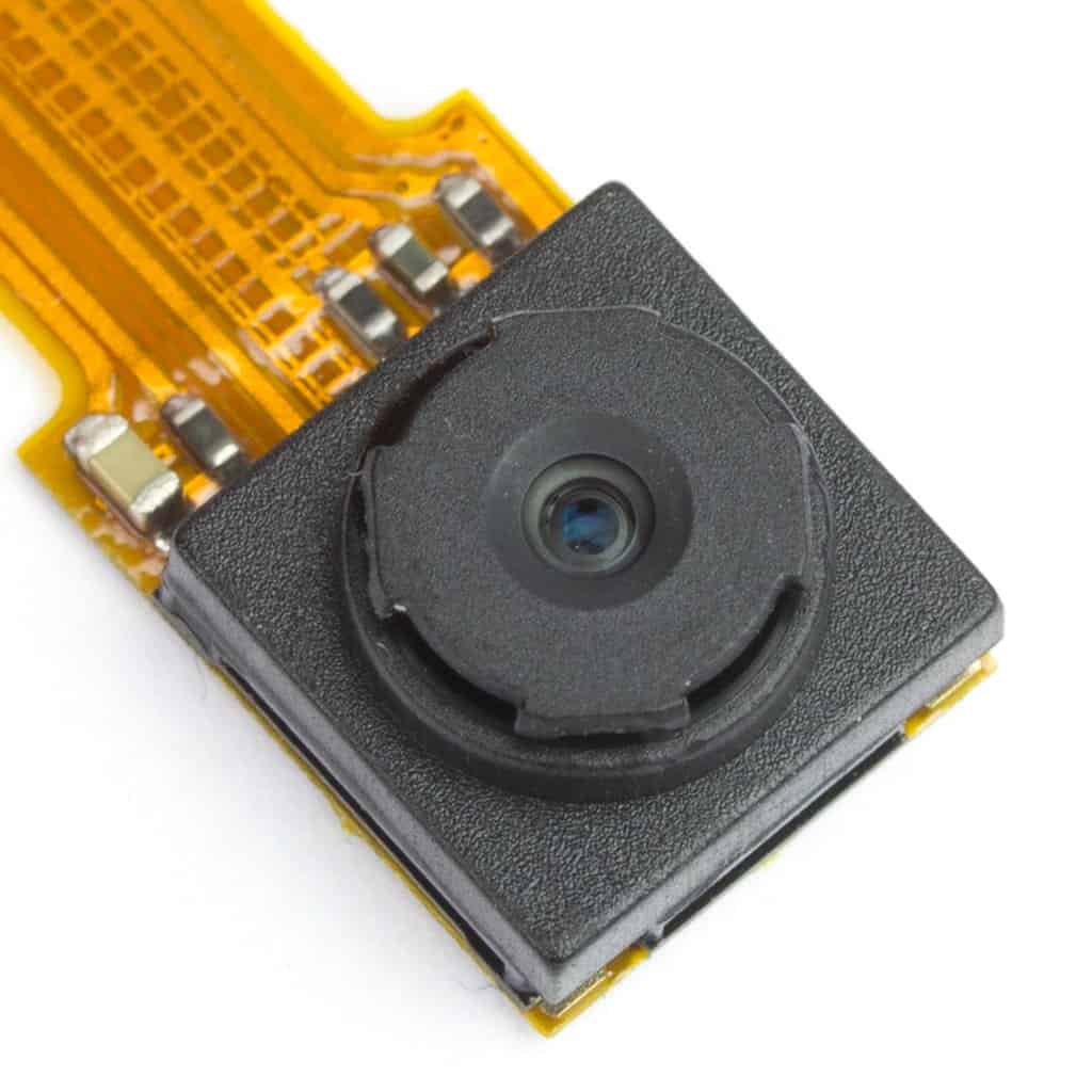
Camera
The Raspberry Pi Zero W CSI camera connector is smaller than the Pi 3 one. If you already have a camera, you will have to buy an adapter to use it. Otherwise, I would recommend to buy this camera module, which incorporates a 5MP sensor (same as version 1 official Pi camera) and can record video at 1080p. It costs 18€. I chose the wide angle camera with IR cut. I know that I will not be able to see anything at night but the use of IR LEDs will increase the energy consumption, which I wanted to keep low. You can always use Philips HUE lights to remotely control your home lights.
Powering Raspberry Pi Zero W
There are a couple of considerations to be made regarding Pi Zero’s power supply. First of all, and unlike larger models, the Pi Zero does not have any regulation or fuse to protect it from over-voltage or current spikes. It means that you should supply a stable source of power with 5 V. The source of power can be connected to the right side micro USB (Pwr In) or to the 5V pin on the GPIO header. Both of them are the same line. Be sure that if an incorrect voltage is applied or a current spike occurs in the line, you will probably damage your Raspberry Pi permanently.
As it has already been commented, consumption peaks of 400 mA with the camera connected have been measured while running stress tests. The Raspberry Pi Foundation recommends a power supply of at least 1.2 A. However, the 0.5 A provided by the buck regulator have been enough for me. Until now I did not found any problems related with the power supply.
Reducing power consumption
Considering that the Raspberry will run from Roomba’s battery, it will be interesting to reduce the power consumption as much as possible. For instance, knowing that the Pi Zero will run headless (without a monitor connected) and will only be accessed through SSH, there is no need to power the display circuitry. Disabling the HDMI port can save up to 25 mA. To do so, just run /usr/bin/tvservice -o (or with -p to re-enable). I have placed a short script in /etc/rc.local which checks if the HDMI cable is connected or not and disables the HDMI port accordingly.
# Get the current video output type and strip away the unimportant bits
video="$(tvservice -s | sed "s/^.*\[\([^ ]*\) .*$/\1/" )"

if [ "$video" != "HDMI" ]; then
        printf "HDMI not detected. Turning off.\n"
        tvservice -off > /dev/null
else
        printf "HDMI detected.\n"
fi
Another way to reduce the power consumption is disabling the LEDs of the Pi. The Raspberry Pi Zero has only one, the activity LED, that blinks every time the SD card is accessed. Its consumption is approximately 5 mA. To totally disable it add this lines in your /etc/rc.local file:
# Set the Pi Zero ACT LED trigger to 'none'
echo none | sudo tee /sys/class/leds/led0/trigger

# Turn off the Pi Zero ACT LED
echo 1 | sudo tee /sys/class/leds/led0/brightness
You can also do this by editing the /etc/config.txt file:
# Disable the ACT LED on the Pi Zero

dtparam=act_led_trigger=none
dtparam=act_led_activelow=on
I am not sure if this will translate into a real consumption reduction, but as it will not be used, you can disable the bluetooth module of the Pi Zero by adding the following line to /etc/config.txt:
# Disable bluetooth on the Pi Zero

dtoverlay=pi3-disable-bt
Finally, try to reduce the software installed and running in the Pi Zero. For instance, use Raspbian lite instead of the desktop version and do not install extra software unless you really need it. The more processes running on your machine, the more consumption it will have.
Other considerations
- It will be very useful to build a reset button in the Pi Zero. This way you will avoid having to disconnect and connect the power supply every time you want to restart the system. To do so, you only have to connect the Raspberry’s holes marked with run with a momentary switch. I have used one of this from Sparkfun.
- You will require a new and fresh MicroSD card with Raspbian Stretch lite or newer. As explained in this post, I would recommend using a card as large as possible. Although the configuration applied here tries to reduce the disk writes, leaving plenty of free space ensures a longer life to the SD cards.
- This tutorial considers that the Raspberry Pi Zero used is running Raspbian Stretch headless. You can read in previous posts how to install Rasbian, create new users and connect using SSH.
Building Roomberry
Once all the pieces have been described, let’s see how to build and run Roomberry, your Raspberry interface with Roomba.
Hardware
My objective was to encapsulate the components (Raspberry Pi Zero, camera module, logic level converter and switch button) in an stable case with easy access to all ports and SD card. The only option that I found, excluding printing my own 3D design, was this one. This case satisfies all the requirements and allows me to attach a HAT (Hardware Attached on Top), an add-on board with the couple of electronic components needed. The following image shows the PCB schema. Note that the Run pins are located in the Pi Zero and not in the HAT. To build it, a piece of a PCB Board of 12 x 10 pins will be enough. To cut the PCB I have used a rotary tool.
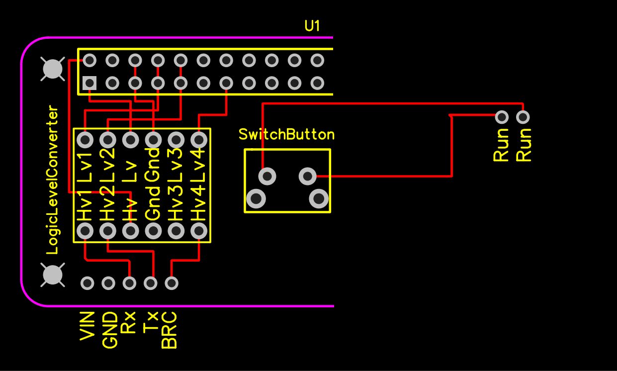
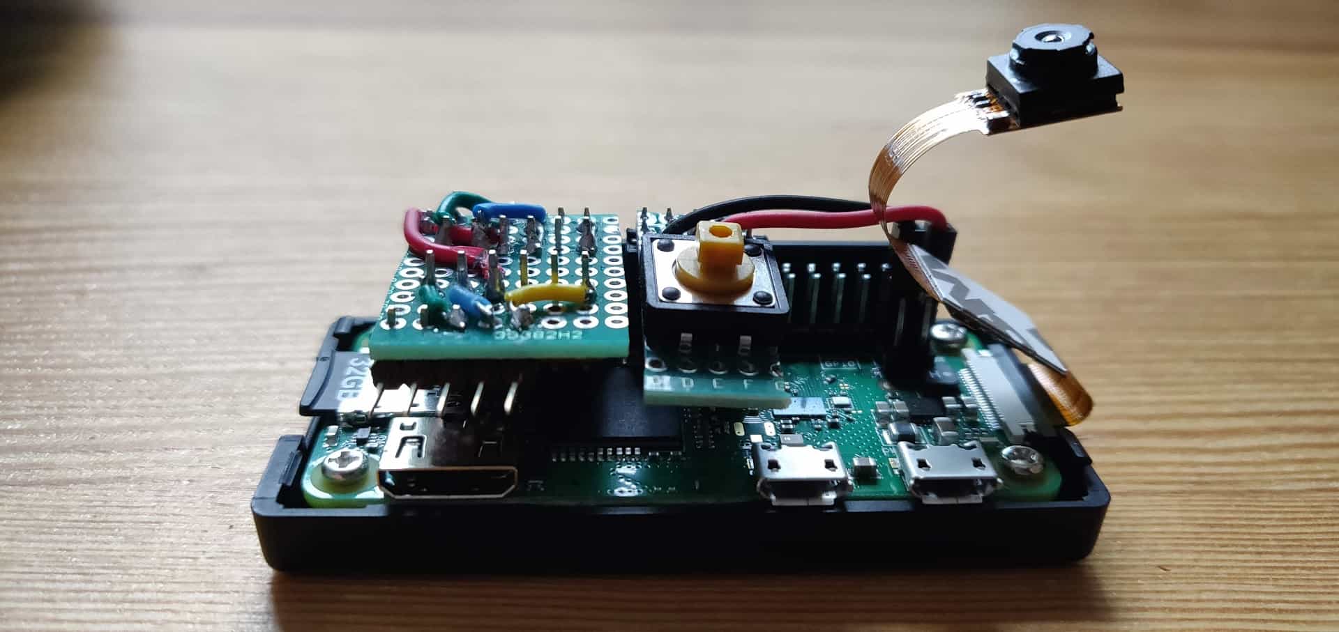
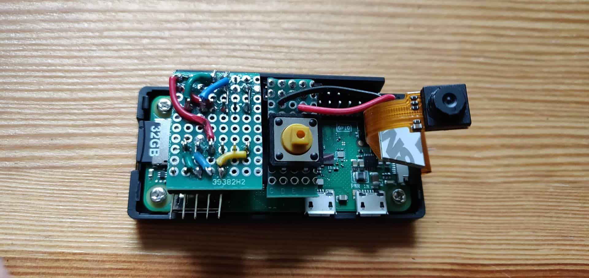
The logic level converter will need both high and low voltage, which can be obtained from GPIO (the Pi Zero includes a step down converter from 5 to 3.3 V named PAM2306AYPKE). I have placed the switching button in the middle of the Pi Zero, as it was an extension of the HAT. By doing so the button’s stem stands out the case so it can be pressed externally. You will have to drill a couple of holes in the case: one for the button steam and another (and bigger) hole for the camera. Moreover, I had to sand carefully the case’ space designed for the CSI connector to make room for a 180-degree turn of the cable. The following pictures show the results:
Software
Configuring Raspbian Stretch
Before connecting Roomberry to the mini DIN 7 connector of the Roomba, a few configuration steps should be performed. Assuming that the Raspberry Pi Zero W is running the last version of Raspbian and is already set up headless:
- Connect the micro USB power supply built in section 2.3.2 to the Pi Zero. After a few seconds the system should be up and running. Open an SSH connection to your pi Zero.
- By default the Pi’s serial port is configured to be used for console input/output. To communicate with Roomba though this port, the serial console login needs to be disabled. You can do it with
raspi-configchoosing menu 5 – Interfacing options and P6 – Serial. Answer No to the question “Would you like to login shell to be accesible over serial?” and Yes to “Would you like the serial port hardware to be enabled?”. Do not restart the system yet. Alternatively you can also comment the console definition and add to the end of file/boot/configthe following line:#Find and comment console definition #console=serial0,115200 ... enable_uart=1
- If you have not done it yet, enable the camera module. Again, you can do it though
raspi-configchoosing menu 5 and P1 option. On the other hand, you can also edit file/boot/configand include these changes (disabling camera led is not required but recommended to save power):start_x=1 gpu_mem=128 disable_camera_led=1
I am not sure which is the optimum quantity of RAM to assign as
gpu_memorywhen the camera module is being used. Until now I have not found any “Out of resource” errors while operating with the camera, so I assume 128 Mb is a good choice. - Disable all swap and mount
/tmpdirectory in RAM Disk with 50 megabytes of space. This location will be used to store ephemeral files, such as camera snaps and Roomba status files. Increase the commit time in/etc/fstabto 30 minutes and include the noatime option in the SD partition. Find the commands in this post. - Now it is time to test if everything is working correctly. Turn down your Pi and connect the serial port to Roomba. Place the Roomba at the charging dock. Boot the system and check that everything is working as expected (and that the robot is not doing anything strange).
- Test reading from serial port: I have used
minicomto read the data sent by Roomba. To install it just type:sudo apt-get install minicom
Connect with the serial port of Roomba by doing:
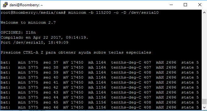
minicom -b 115200 -o -D /dev/serial0
If your Roomba is charging you should see a text similar to following image reporting the charging state of the Roomba every second. Press CTRL + A and X to exit
minicom.
- Test writing to serial port: you can run a short Python script that will write to serial port. First of all, you will need to install
pyseriallibrary (to access serial port):sudo apt-get install python-serial python3-serial
Now open an interactive python2 shell (just type python2, will not work with python3) and run this code (line by line):
import serial
import time

# Open a serial connection to Roomba
ser = serial.Serial(port='/dev/serial0', baudrate=115200)

# Assuming the robot is awake, start safe mode. Note that 0x83 in hexadecimal corresponds to 131.
ser.write('\x83')

time.sleep(.1)

# Start cleaning - 135
ser.write('\x87')

# Stop (back to off mode) - 173
ser.write('\xAD')

# Close the serial port; we're done for now.
ser.close()
If the robot started a clean cycle after the 4th instruction and stopped after the 5th, congratulations! If one of these last two steps did not work, something may be wrong with your
hardware (probably on the prototyping board). Have a look at the connections and retry.
Dependant Libraries
First of all, to interact with the robot and the camera attached to Roomberry I have used a couple of third party libraries. You will need to install them before proceeding:
- To operate the camera use
picamera. This package provides a pure Python interface to the Raspberry Pi camera module (both V1 and V2) for Python 2.7 (or superior) or Python 3.2 (or superior). It is usually installed by default in Raspbian distributions. Try it by typing:python -c import picamera
If you get no error, you got
picamerainstalled. If you receive an import error, install the module first by running:sudo apt-get install python-picamera python3-picamera
- There are a few implementations of iRobot Open Interface for different programming languages. I wanted to learn Python more deeply so I decided to use Matthew Witherwax‘ irobot library. All the functions documented in the OI Specification are implemented. I have corrected a few bugs in the code and created a new repository, available in my Github. A couple of improvements / adaptations have already been done:
- Allow the use of an alternative wake up function using the Raspberry’s GPIO Pin connected to the Baud Rate Change Pin of Roomba (default wake up function uses serial’s RTS pin).
- Enable history in the REPL python console.
- The Roomba prints after waking up or while charging some information regarding its status. A flush of the serial port before every read operation is done now to avoid issues with this unexpected messages.
- To avoid trying to waking up the robot before entering in power safe mode, I have removed the 15 seconds margin included in the
handle_auto_wakeupfunction. - Connected with previous point, in case a command does not receive an answer, a wake up pulse is immediately sent (just in case the robot is sleep). If the command is repeated, it will be correctly replied.
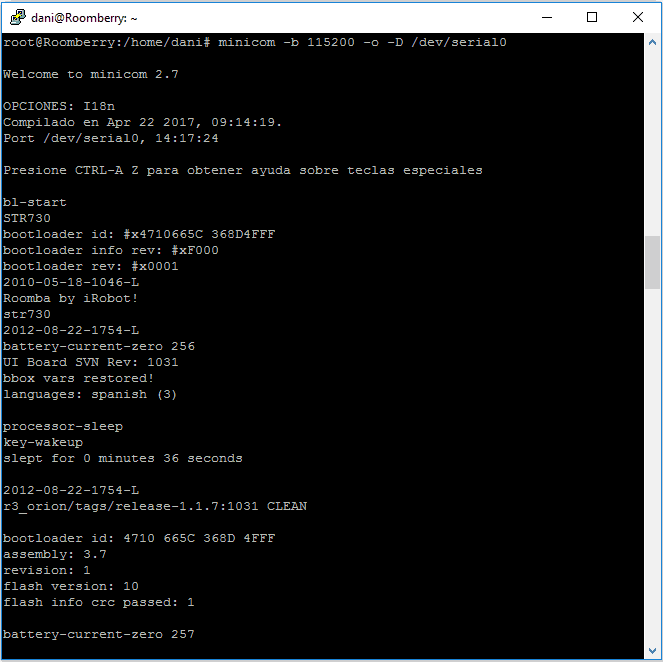
- There was a bug in the distance and angle measurement in old versions of Roomba. The issue was solved in release 3.4.1. Distance and angle can also be approximated from wheel’s quirks. The creator method of this library tries to obtain firmware version by rebooting Roomba and parsing the welcome message. By this way it can decide to use the distance reported by the robot or the alternative based on quirks. Unfortunately, new versions of the robot (series 700 and 800) does not print firmware version in the welcome message at startup. I have removed the reboot operation and added the option to use quircks approximation as a parameter in the creator method.If you want to know your Roomba’s 700/800 firmware version, open a minicom console and wait until the robot enters sleep mode (5 minutes without interaction). Press then any button (or send a wake up through the GPIO). The robot will report, among other information, the firmware’s release as can be seen in this figure.
- To use irobot library download the last release and install it using
pip(I usedpip3):mkdir /tmp/irobot wget https://github.com/danimaciasperea/irobot/archive/1.0.0.tar.gz -P /tmp/irobot/ pip install /tmp/irobot/1.0.0.tar.gz
Depending on the version of pip used (
pip -version) the library will be installed in a different folder/usr/local/lib/pythonX.Y/.
Let’s do now a short test. Run the following instructions (I am using Python3 but the library is fully compatible with Python 2.7 too). Remember to update the library path depending on thepipversion used:python3 /usr/local/lib/pythonX.Y/dist-packages/irobot/console_interfaces/create2.py Launching REPL Serial Port> /dev/serial0 BRC Pin> 27 Enable quirks> No Create2 attached as robot on /dev/serial0 May it serve you well robot.clean() robot.stop()
If everything works fine you will be able to control interactively your Roomba though this console.
Installing Roomberry daemon
To interact with Roomberry I have developed a Python 3 program that creates a multithreading web server. This code is intended to run as a daemon and handles the HTTP GET Requests performed against Roomberry. The commands sent to the robot are encoded in the request’s URL query string. The URL path should start with cam or roomba depending on the device that will execute the operation. If the command needs one or more parameters, they should be just passed as a field-value pair in the query string. For instance:
#Send a clean command to Roomba
curl 'roomberry/roomba/?op=clean'

#Drive Roomba straight at 20 mm/s
curl 'roomberry/roomba/?op=drive&velocity=11&radius=32768'

#Set camera saturation to 65
curl 'roomberry/cam/?op=cam&saturation=65'

#Download picture taken 20180810 at 102849
wget roomberry/cam/20180810/20180810-102849.jpg
Download the code from my Github repository. Install the required libraries and configure your IFTTT key, as well as the log path, before launching it. Wrap it with a service to start it automatically every time the Pi Zero boots up. In this entry you can find more information on how to do it.
wget https://github.com/danimaciasperea/Roomberry/archive/1.0.0.tar.gz -P /tmp/
tar -xvf /tmp/1.0.0.tar.gz -C /tmp/


#Before doing next step, adapt the code to your environment (serial port used, IFTTT Key, etc.)
sudo cp /tmp/Roomberry-1.0.0/roomberry/roomberry.py /usr/local/bin/
sudo cp /tmp/Roomberry-1.0.0/roomberry/roomberry.service /lib/systemd/system/

sudo systemctl enable roomberry.service
service roomberry start
Some considerations regarding the code:
- Each request starts a handler thread so, to avoid concurrent access to the robot or the camera, Lock objects are used.
- A log file is created reporting each request received (IP, datetime and url), as well as errors handled. Edit the daemon configuration to change the location/name of the log file. Change the log level from DEBUG to ERROR or CRITICAL to reduce its verbosity.
- An additional thread is created to evaluate periodically Roomba’s battery level. It will also close the camera after a certain number of seconds of inactivity to reduce battery consumption and memory usage. If the battery level is too low, Roomba will be sent home (
seek_dock()operation). If the battery reaches a critical level, Roomba will be stopped and the Pi Zero will be immediately turned off to avoid battery damage. IFTTT notifications are sent in both cases. Update your IFTTT key to use this functionality or comment lines 135 and 143 to skip it. Find a guide on creating IFTTT events in this post. - The pictures and recordings taken are saved in Raspberry’s SD Card. Upon request, the web server will serve them.
- The server will create and send XML files to report the status of the robot, the camera and the multimedia files generated. This files, as they will be frequently updated, will be placed on
/tmpdirectory (recommended to be mounted in RAM memory). - As a design decision and with the aim of reducing resource consumption in the Pi Zero, it has been decided to perform all the communications in plain text without encryption or authorisation. For this reason it is strongly advised not to allow direct communication with the Pi Zero trough the internet. In my case, the Raspberry Pi that I use as the “brain” of my domotic system is the only device authorised to talk with the Zero. You can easily achieve this by adding rules in
iptablesas explained here.
Web interface
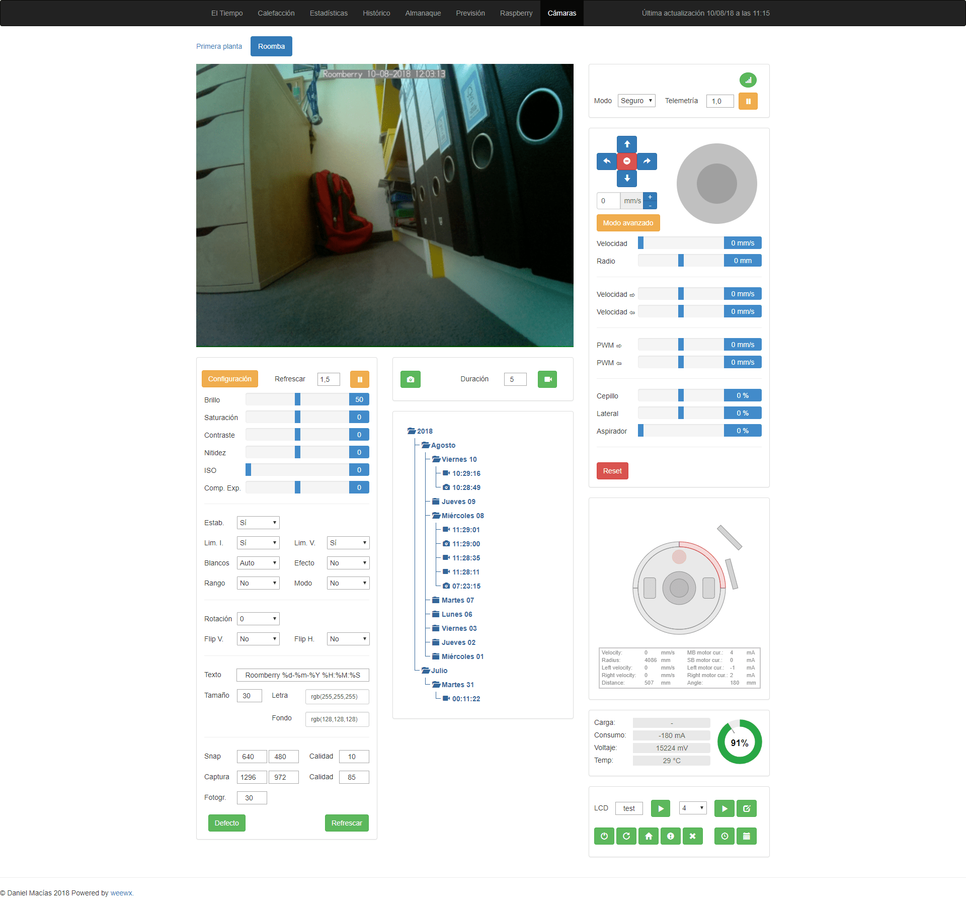
In order to control Roomberry in an easy way I have developed a simple web interface. You can see a demonstration of how it works in the video at the beginning of this post. To use it you will have to include your Roomberry’s IP in the /etc/hosts file of your Raspberry to point the right address. Without being exhaustive, those are the main characteristics of the web application:
- I have followed Bootstrap framework (HTML5 and Javascript with AJAX requests) and PHP in the server side. This web interface is served by my main Raspberry Pi (not in the Pi Zero!) running apache2 with PHP enabled.
- This web requires password authentication and all the communications performed are encrypted. As previously commented, only the information exchanged locally (in my local network) between the main Raspberry Pi and Roomberry travels in plain text. The requests are done in the server by PHP using
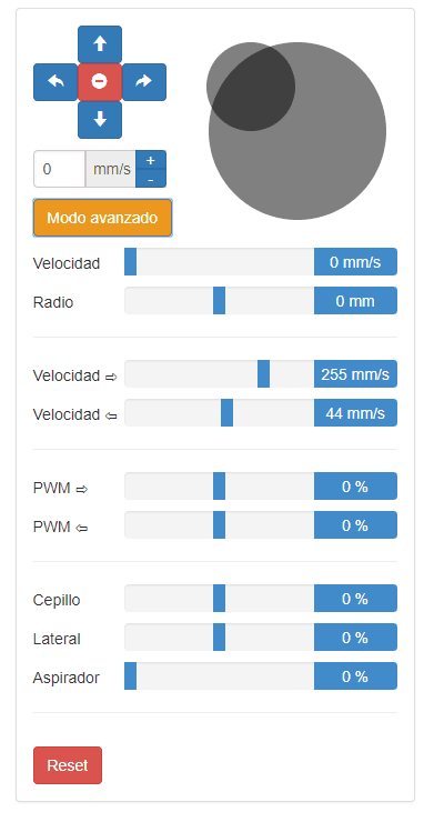
libcurllibrary. This way, if a video is required, the main Pi will forward the request to Roomberry, who will sent it first to the main Pi and who latter will serve it. I know that this is not the most efficient approach but in this project security was my first priority, considering that somebody could eventually gain access to a robot with a camera placed at my home. - To control the movements of the Robot I have used nippleJS to draw a virtual joystick that sends commands to the Roomba. Alternatively, the four main directions (forward, backward, left and right) and speed can also be manually set. In the advanced section of this panel the speed, radius as well as the PWM (Pulse-Width Modulation) of all the motors (brushes and wheels) can be controlled.
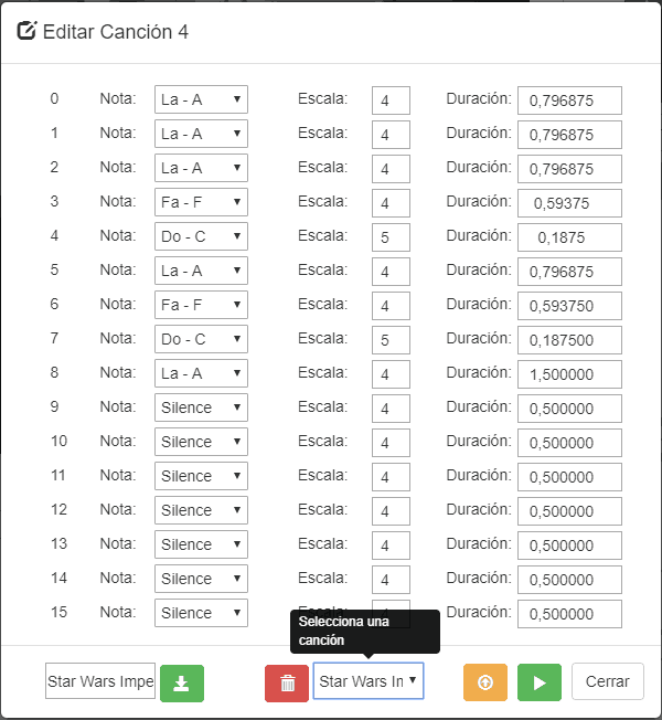
- Roomba can be configured to play songs as explained in the documentation. ToneJS is used to produce notes and test songs before sending them to Roomba. The songs can be saved in disk and recovered later.
- To show Roomba’ status I have used several solutions. For instance, Roomba’s battery level is depicted in a circular gauge with Justgage plugin. Other information is showed in standard HTML labels while a graphic with Roomba’s sensors is depicted using HTML5’s canvas. The drawing, as well as the rest of elements, are refreshed periodically depending on the
telemetry_refreshvalue.
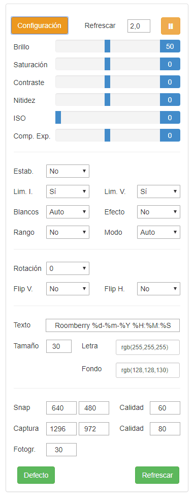
- Camera controls are standard HTML buttons, selectors, spinners and inputs. The refresh of snap buttons can also be adjusted.
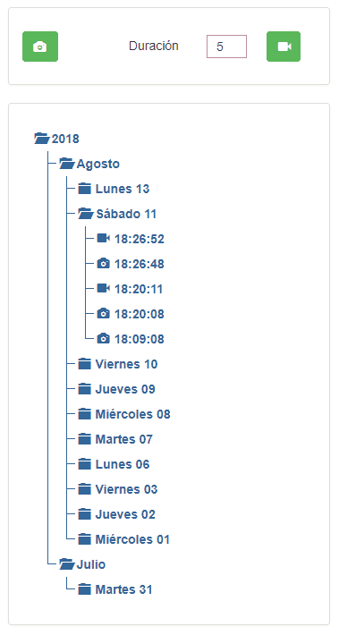
- Finally the pictures and videos taken are shown in a tree. Clicking in one of this elements will open a new modal containing the photo or video requested.
To make everything work you should install in the Raspberry Pi where the Apache server runs the following libraries:
Curl Library: sudo apt-get install php5-curl

XML parser Library: sudo apt-get install php5.6-xml

MP4Box: sudo apt-get install -y gpac
And be sure that the folders/files served by apache belongs to user www-data:
sudo chmod -R www-data:www-data /var/www
Next Steps
- Roomba’s model 700 enters into sleep mode although the BRC pin is pulled down periodically. This is not a big problem because, when a command does not receive an answer, a wake up pulse is immediately sent. If a new command is sent, it will be correctly replied. However the first one will not be received by the robot, causing the throwing of an exception in the Roomberry log. Maybe doing some more research I can find a way to avoid this error.
- Although there are methods to stream real time video with a camera module and Raspberry, I have not found a way to integrate it in a third web without big delays and quality problems when using a Pi Zero. For this reason, I use in the web app snaps (pictures) refreshed frequently instead of videos.
- I have postponed for a second version of Roomberry the functionality of detecting movement and recognising objects through the camera. The Pi’s camera is capable of outputting the motion vector estimates that the camera’s H.264 encoder calculates while generating compressed video as explained here. It should not be very difficult to create a new thread that, in case of motion detection, saves the last seconds of the video in disk automatically. However I would like to explore also the possibility of using OpenCV to search something in the house like, for instance, my dog. I will have a look on this in the future.
- An interesting function to control the robot would be to order a movement or turn for a certain number of millimetres or degrees.
- As this is my first project coded in Python, there is still a lot of room for improvement and optimisation. I will try to keep an eye on this in next iterations.
Hello, thanks for sharing this great project with us. I run into some installation issues though.
pi@raspberrypi:~ $ wget https://github.com/danimaciasperea/irobot/archive/irobot-1.0.0.tar.gz -O /tmp/irobot/
gives the following error message :
/tmp/irobot/: Is a directory
Any clue what’s wrong ? Thanks !! Kind Regards, Tony
Sorry Tony, it was a typo mistake.
It should say -P and not -O.
I have corrected the guide.
Thanks!
Dani
Hi Dani,
Such a nice and well explained tutorial. I just have a problem with the Roomba. Most of the instructions are working unless stop() and power_down().
I’m using an iRobot create2, connecting the USB cable to the RPi. Runing /console_interfaces/create2.py. The input and output is the following:
Launching REPL
Serial Port> /dev/ttyUSB0
BRC Pin> 5
Checking firmware for quirks
Restarting Robot…
Could not determine firmware
Enabling quirks for safety
Create2 attached as robot on /dev/ttyUSB0
May it serve you well
When I type clean and I want to stop; sometimes the Roomba produces a beep but it doesn’t stop and trying with power_down simply doesn’t respond. Is there something related to the firmware or hardware perhaps?
Thanks in advance, Abraham
Hi Abraham,
I am not sure where the problem can be. If all the commands works fine except this two, my guess is that, as you pointed out, the problem is related with the firmware version of the Roomba.
What Roomba model do you have and what version of the firmware is installed?
Do you have the same problem when launching the stop / power down command directly from an interactive python shell?
Hi Dani,
I really appreciate your help. I’m not sure which is the firmware, is it 3.5? Anyways, I copy-paste the commands from the minicom below:
2016-02-08-1606-L
r3-robot/tags/release-3.8.1:6188 CLEAN
bootloader id: 4719 5964 7AC4 BFFF
assembly: 3.5-lite-batt
revision: 2
flash version: 10
flash info crc passed: 1
battery-current-zero 255
bl-start
STR730
bootloader id: #x47195964 7AC4BFFF
bootloader info rev: #xF000
bootloader rev: #x0001
2007-05-14-1715-L
Roomba by iRobot!
str730
2016-02-08-1606-L
battery-current-zero 256
2016-02-08-1606-L
r3-robot/tags/release-3.8.1:6188 CLEAN
bootloader id: 4719 5964 7AC4 BFFF
assembly: 3.5-lite-batt
revision: 2
flash version: 10
flash info crc passed: 1
estimate-battery-level-from-voltage 2521 mAH 16226 mV
battery-current-zero 256
bbox vars restored!
languages: english (0)
Also, I’m using the python shell to test the commands. To be honest, I haven’t tested all of the “method” commands; however, I have tried some that put the Roomba into motion, and I would say I wanted to differentiate into two categories:
1.-(drive, drive_straight, spin_left, spin_right)
2.-(clean, clean_stop, seek_dock)
When I’m using the commands of the “1st” category, they work well, I can stop the Roomba by: drive_straight(0), and I can introduce the “2nd” category commands; unfortunately, once using the “2nd” category, the Roomba doesn’t respond any more to any commands, typing stop() I can listen to the bleep but it keeps going.
Thanks for your time to answer my question, greetings!
Abraham.
Hi Abraham,
I think I can guess what is going on.
Roomba has 4 operating modes. There is a short summary here: https://domoticproject.com/roomberry-surveillance-robot-roomba-raspberry-pi-zero-w-camera/#Roomba_OI_modes.
While Roomba is in Full or Safe mode you can use any of category 1 and 2 commands. However, when you send a category 2 command (Roomba’s documentation name them Cleaning Command), Roomba’s OI mode is changed to Passive mode and will no longer respond to category 1 commands (Actuator Commands).
On the other hand, the Stop command will not stop the Roomba, but will stop the OI, changing the OI mode to Off. While your Roomba is in Off mode, you cannot interact with it at all (for this reason it stopped to react to your commands).
If you send a Clean Command and want to stop it, just send a Clean Command again and the cleaning cycle will be paused. You can use too command Power to power down the robot.
A full description of available commands, required OI modes and changes of mode can be found in Roomba’s OI specification (https://domoticproject.com/wp-content/uploads/2018/08/iRobot_Roomba_600_Open_Interface_Spec.pdf).
I hope it helps. Have fun with your Roomba!
Dani
Hi Dani,
Thank you so much it works fine! It was a big whoa, now I can understand more about the modes, thanks for the tutorial and the information.
Good luck with everything!
Abraham
Hello Dani: First I wish to congratulate you on a great robotics project and a wonderful tutorial. I have found an original iRobot iCreate. I would love to program this (Roomba 400 series) with python. I was wondering if you had any thoughts about using your API with the original Create. I am under the impression that the original Create’s OI is now a subset of the Create2 OI. With that in mind, I hope that the basic control functions in your Create2 API will work. Your UI is amazing. Maybe That will work with the Original Create. Thanks again
Hello Byron,
Thanks for your input. I think it should be relatively easy to adapt the Create2 API to the original Create. You can fork the irobot library (https://github.com/danimaciasperea/irobot) and include there the differences between both specifications (if any) as well as include the functions that only create can (I think it can send IR commands to other Roombas).
I found the specification of Create here: http://hackerspace.cs.rutgers.edu/library/iRobot/Documentation/OpenInterface_v2.pdf
Have fun!
Daniel
Thank You for the information Daniel: I am off to play with my old Create and your new code. I look forward to reading about your future experiments with buttons and electricity.
Thanks
Byron
Hello Dani
This is a really inspiring project ! Do you think would be possible automatically stop the robot when raspberry (for any reason )poweroff ?
cheers
gian
Hi Gian,
If the Raspberry’s power is suddenly cut off, I don’t think there is a way to stop automatically the robot.
Otherwise, if the Raspberry turns down because it detects that the battery is too low or something like this, you can always send an stop command once the shut down is detected. Other option would be to create an script that runs automatically when the system enters in run level 0.
Regards,
Daniel
Hi Dani
Thank you very much for your reply !
I was meaning , if I program a trajectory from the Raspberry and the raspberry for some reason poweroff or become faulty(or eventually the usb/serial converter is faulty ) the robot continues its trajectory without control.How would be possible in your opinion with a keepalive system on the TX/RX channel to implement this feature ?
For example an arduino counter attached to the serial that send a reset signal to the roomba firmware when ( after a specific amount of time ) there is a specific condition on the signal levels of the serial ?
Thanks in advance for your advices !