Contents
Introduction
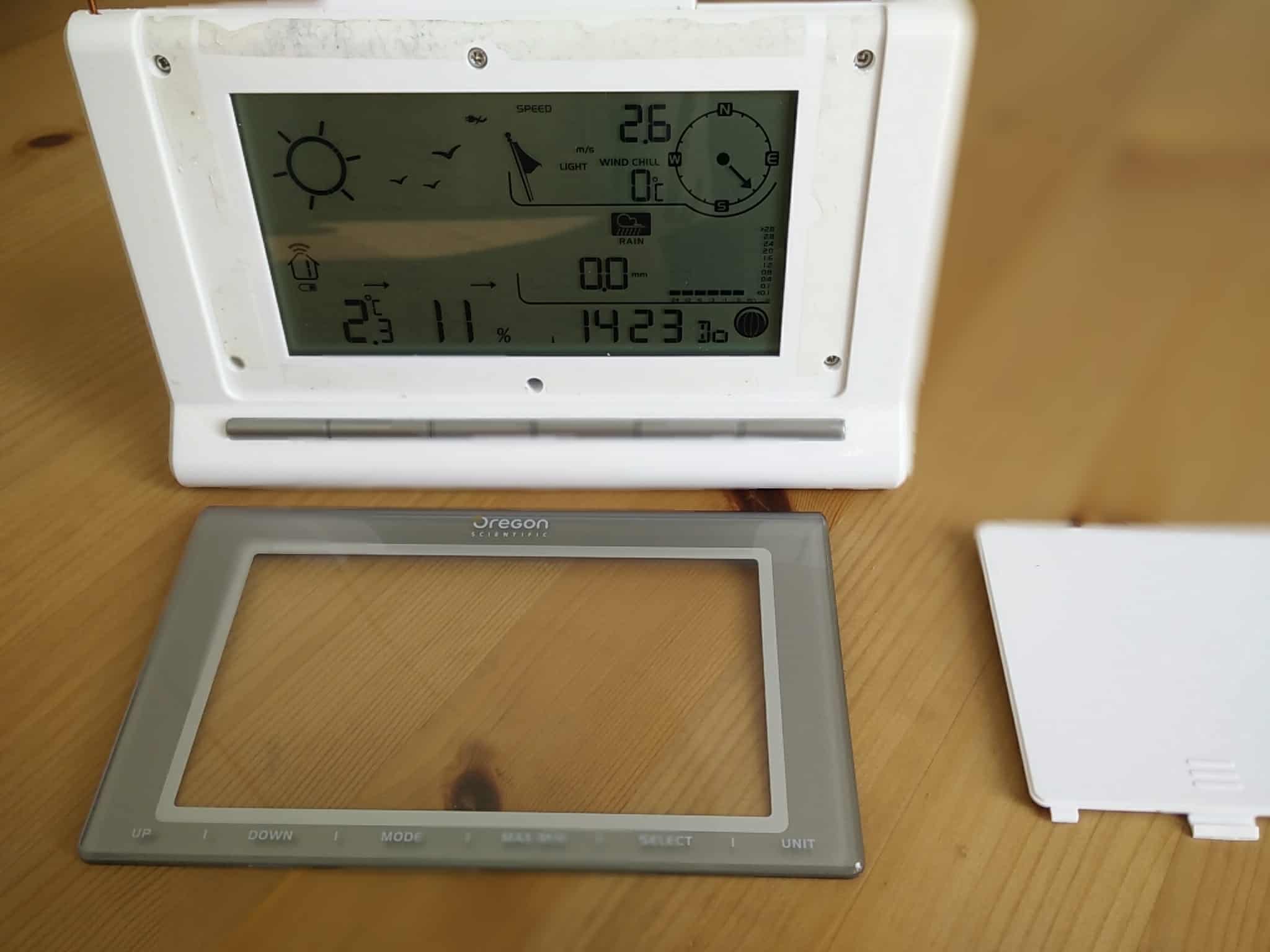
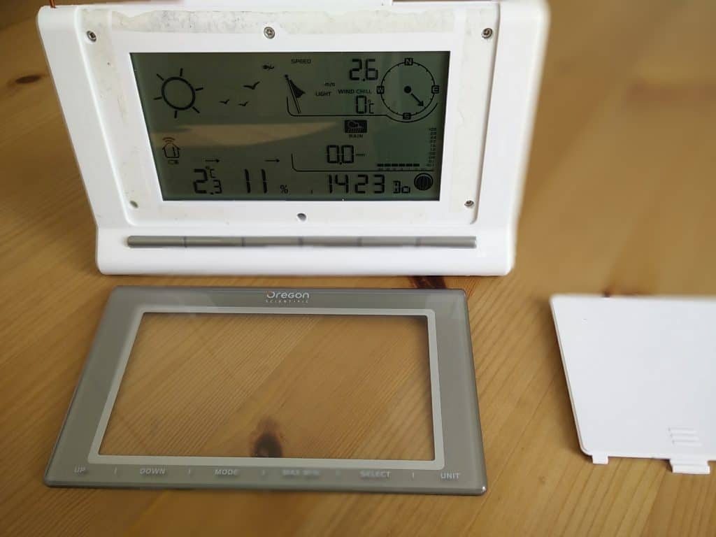
After more than 5 years working perfectly, my WMR88 Oregon Scientific Station started to show reception problems. Periodically the contact between the console and some of the outdoor sensors was lost. The unit normally reconnects after a few minutes but on some occasions the base station and the sensor required resetting. I noticed that the connection problems were solved when the sensors were brought closer to the console. Probably after so many years the RF antenna reception in the console was loosing sensitivity. Maybe the emission of the sensors was loosing strength too. To solve this issue I decided to disassemble my central unit and replace its built-in RF WMR88 antenna by an external one. I will expose the steps followed in this post.
The sensors
I use Oregon Scientific sensors compatible with protocol 3.0. They all perform RF transmissions using on-off-keying (OOK) with Manchester coding on a carrier frequency of 433.92MHz. RF transmissions do not occur on an exactly regular time boundaries to avoid signal overlapping. Some clever people have decoded protocol 3.0 of Oregon using reverse engineering. Find an specification in this link.
Each sensor has a built-in transmission antenna. The antenna signal strength will depend, among other factors, on the location, relative humidity, RF noise, level of battery, etc. If you have connectivity issues make sure that you are using good quality and fully charged batteries. Reset both the wireless sensor and base console and bring the sensor indoors, within 2 meters of the console. If it still doesn’t work, you may have another type of problem that will certainly not be solved with this tutorial. If you get good reception with the sensor located near the console, but lose reception when the sensor is outside at a greater distance, it may be worth to keep on reading.
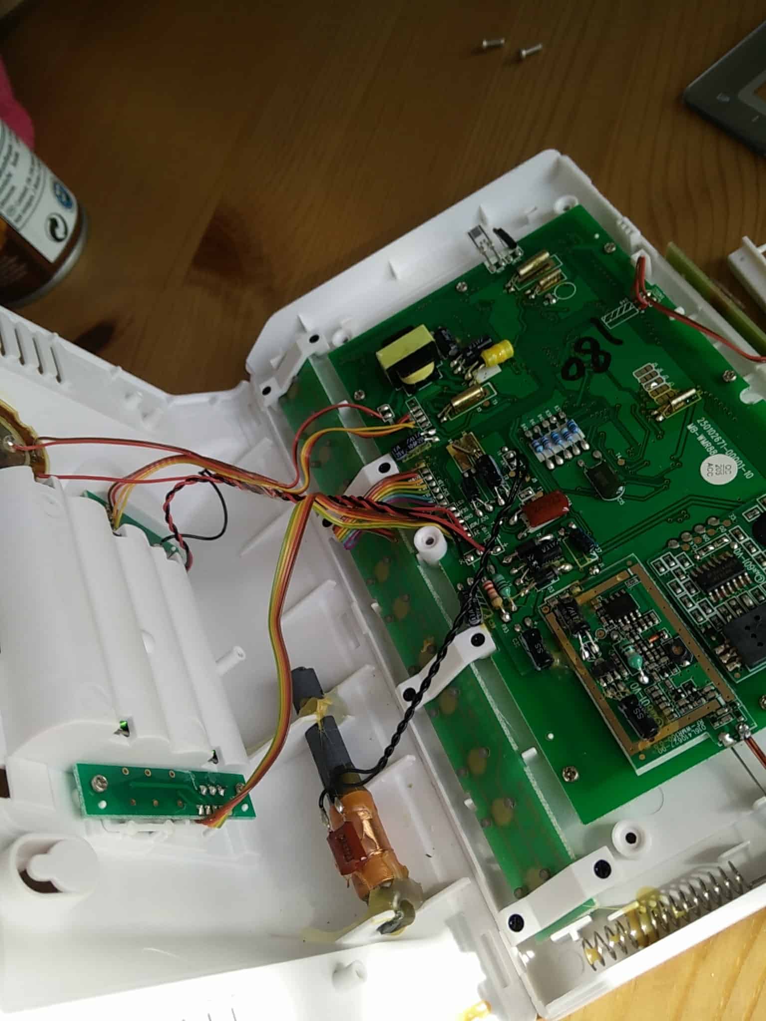
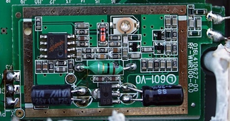
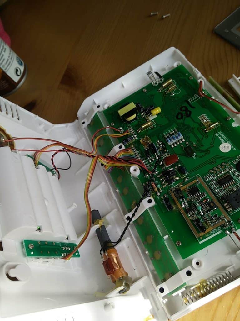
The central unit
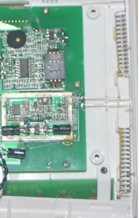
The central unit is equipped with a wireless receiver named RF-WMR100 connected to a balanced dipole antenna. At the antenna terminals there is a balun transformer. It will convert the signal from a balanced source to the unbalanced input of the RF-WMR100 circuit. A common problem in Oregon Scientific Stations is that the receiving built-in antenna does not not have enough sensitivity to pick up the sensors’ signal.
To increase the sensitivity, first consider using a plugged DC adaptor. It will improve the transmission range, as the circuit ground also is a part of the antenna. You can also try to move the unit away from RF noise sources or metallic elements that may introduce interferences. WiFi access points, fluorescent light ballasts, LED lamps and TV are potential noise sources. In general, all consumer electronics devices can generate noise, so just try to move your central unit to different places in your house and observe if you get new signal drops.
If it does not help, you should decide if it is worth to modify your console to improve reception by replacing the internal antenna. Alternatively, or in case your WMR88 station stops working at all, there is a very well documented project in Github to replace it with an Arduino board and a couple of electronic components.
Some antenna basics
Before starting with the hardware part, lets calculate the theoretical length of the new antenna. First of all we need to calculate the wavelength of the frequency, in other words, the distance over which the wave’s shape repeats. The wavelength λ is given by:
λ = v / f
where v is the the speed of the transmission and f is the (average) transmission frequency. In air, v is equal to c, the speed of light, which is 299.792.458 m/s. The wavelength for the 433 MHz band is thus 299.792.458 / 433.000.000 = 69.24 cm.
As we are working with dipole antennas the ideal theoretical length is 1/4 wavelength long, which is 17.3 cm. However, antennas behavior are sometimes hard to predict. So I think it will be better to start with 25 cm and trim the wire until performance improves.
Replacing WMR88 antenna
Before starting disconnect your unit from power plug and remove the batteries. Remember that any manipulation will void the product guaranty.
- Disassemble your WMR88. To do so, pry off the top plastic bezel to reveal screws. This front windows is pretty solidly glued, so just keep prying carefully, eventually it will come off.
- Screw off and separate the housing in two parts.
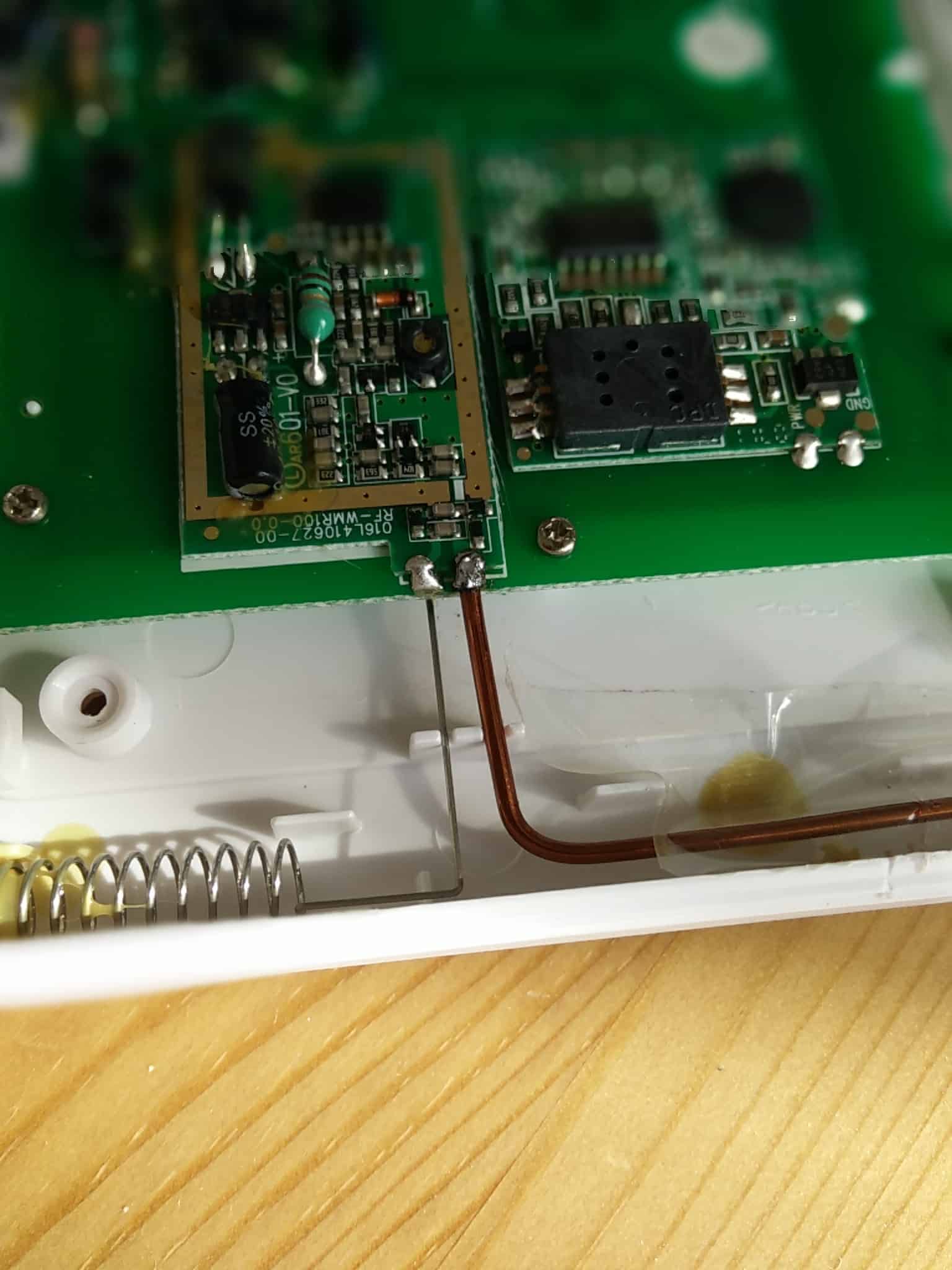
- Make a hole in the top of the plastic case, directly above the coil of wire. The housing’s plastic is not very hard, you will be able to make this hole with a pliers.
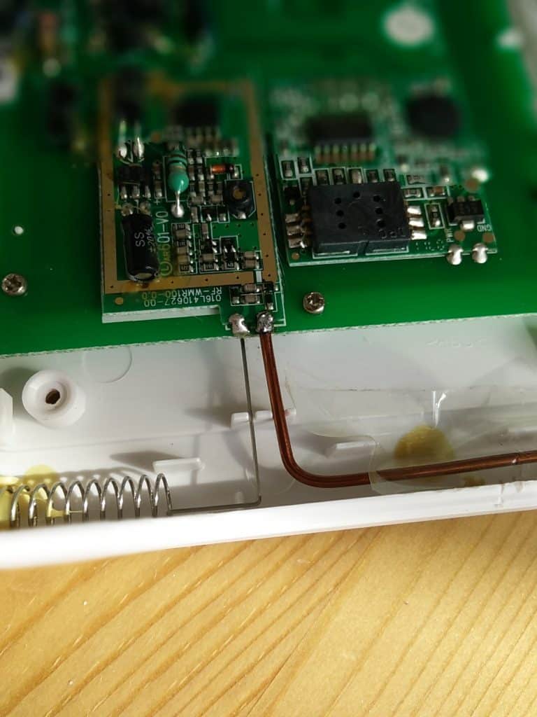
- Use an iron to unsolder the upper antenna from the PCB. Some people have left the original antenna. They will for sure interfere with each other. I found better results by removing it. As often happens in the world of antennas, sometimes an antenna just works and it is not worth the trouble to figure out why.
- Get a piece of 1,33 or 1,55 mm of copper wire (16 or 18-gauge) measuring 25 centimetres. Support it in the hole you drilled in the case and run it down to the PC board, making a right angle bend. Solder it to the wireless receiver circuit.
- Re-assemble the case and see how it works. I didn’t need to re-glue the plastic bezel. The old glue was sticky enough to hold the window when putted back on. If you’re not happy with the reception, then start trimming the length of the copper wire in very short increments of 0,5 cm. Wait some time before starting trimming to see if there are differences in the reception. Each sensor has a different transmission rate, but in around 60 seconds all the sends should be performed.
2 thoughts on “Adding an external Antenna to WMR88”